¶ ACE ROUTER LOGIN
Open Internet Browser and enter default IP of the router http://192.168.100.1
The default login credentials are mentioned at the bottom the ACE Router appliance.
NOTE:
Change the default password after login to avoid un-authorized logins to the Router.
¶ AnexGATE ACE Dashboard
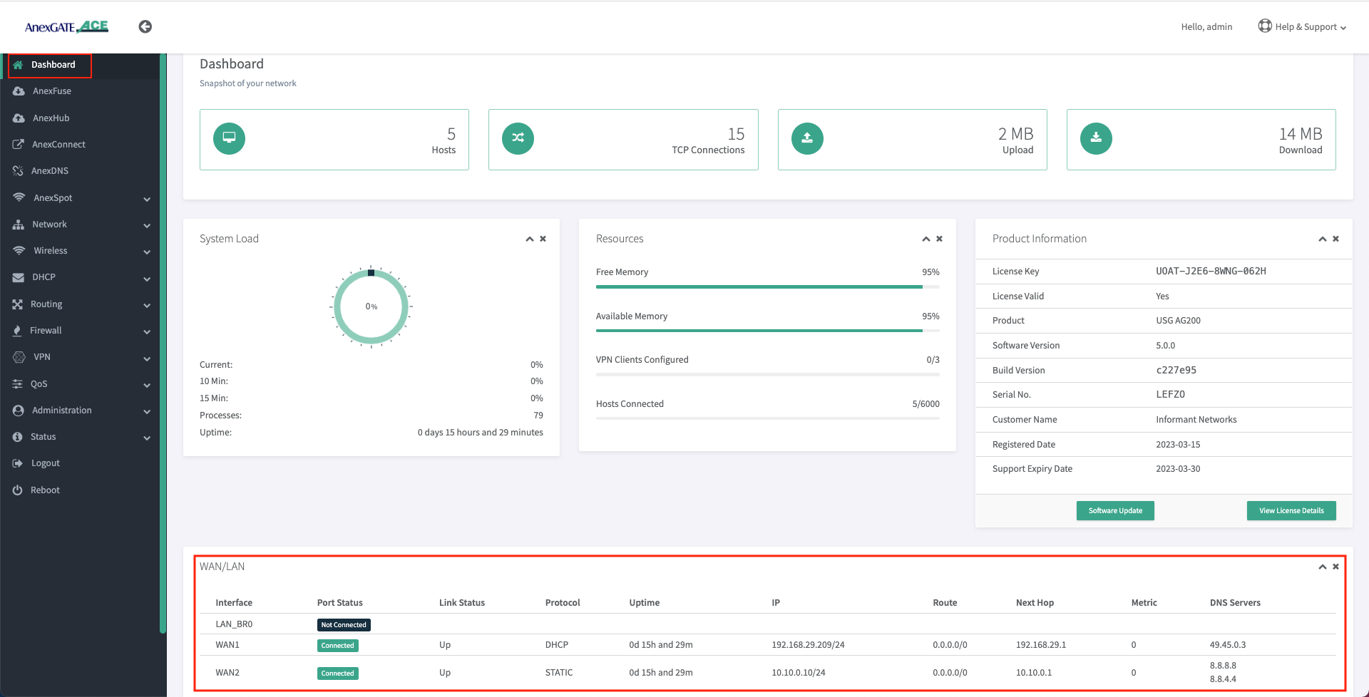
Dashboard allows you to view the status of the device such as Hosts, TCP Connections, System Load, Download/Upload statistics, Connected LAN/WAN Interfaces, Product Info & status of the License and various other link statistics in one single pane as shown below.
¶ Setting up LAN Interfaces
LAN can be configured on any port of the AnexGATE router.
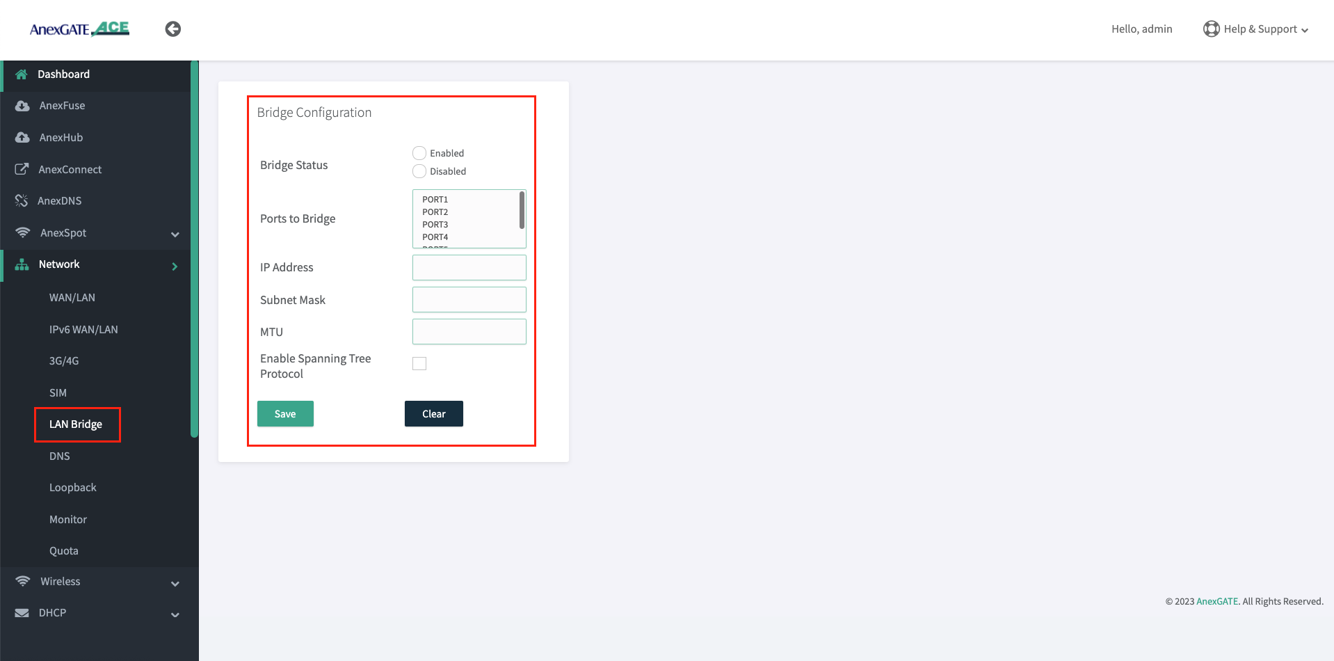
Lan Bridge- To configure LAN Bridge, Go toNetwork - Lan Bridge.LAN Port- To configure LAN port, go toNetwork - LAN/WAN.
Configure LAN Bridge Port
¶ Configure LAN Port
Before configuration of LAN Port, Unselect the Port which are already member in the LAN Bridge by going into Network - Lan Bridge.
Once the Ports have been removed from the LAN Bridge membership. Configure the port as a LAN (Non-Bridge) port.
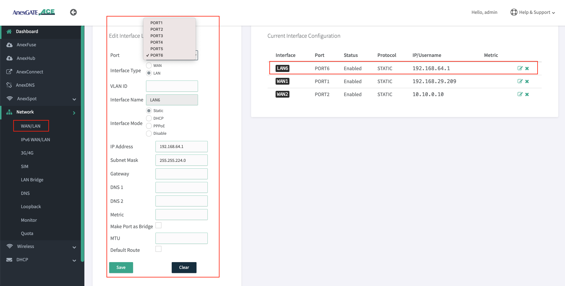
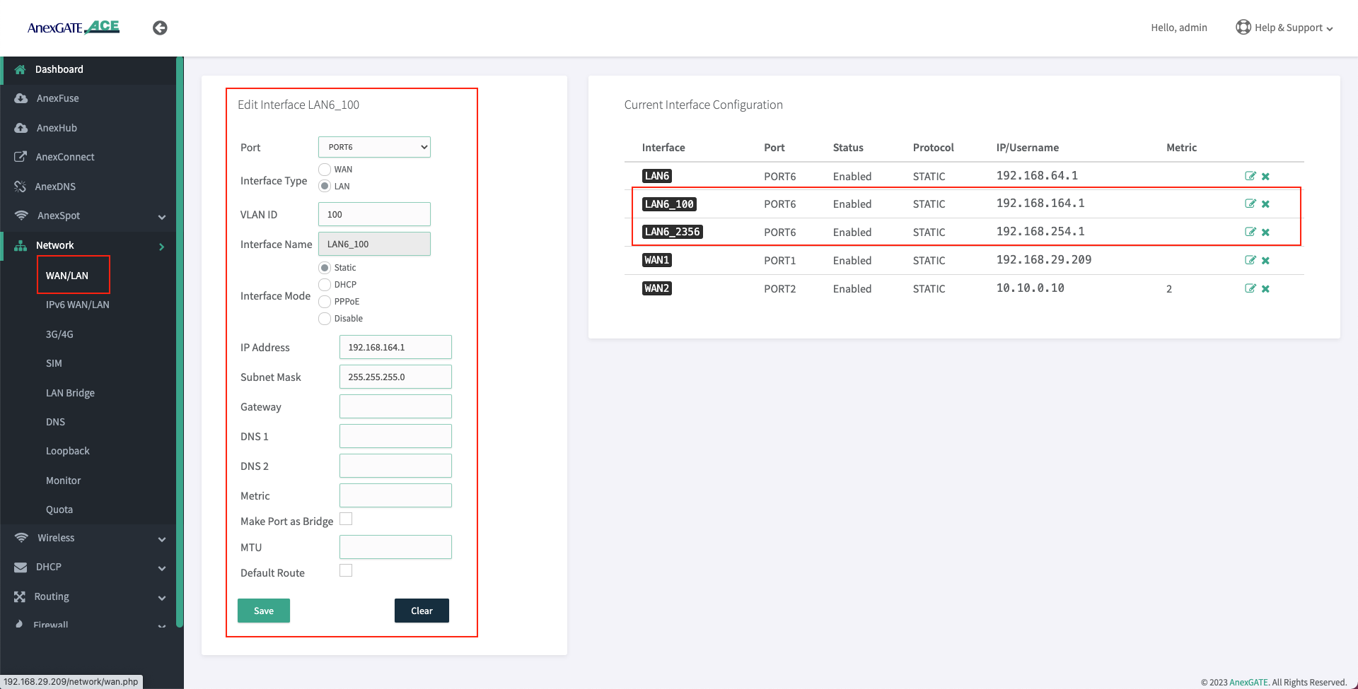
- To configure an individual port as
LAN Port. Go toNetwork - LAN/WAN. - Select Port number, Interface type, interface mode and assign IP address on a port which is to be configured as LAN.
The AnexGATE ACE Hotspot router has capability of configuring multiple LAN/vLAN interfaces as shown in the image below.
- Confirm the reachability between newly configured LAN Port and the PC-system by ping.
- Once the Delete the LAN Bridge configuration by going to
Network - LAN Bridge
Note:
- LAN Interface must be configured using Interface mode as “Static” and no metric has to be mentioned. The LAN interface configured acts itself as a gateway so there is no need to assign gateway.
- LAN Bridge interfaces must be removed in order for the AnexSPOT to work properly.
Warning:
Before disabling or deleting any default interfaces such as LAN_br0 to configure AnexSPOT. Make sure that different LAN has been configured on other port and is in working condition by testing connectivity towards router and PC-machine.
¶ Configure VLAN
- To configure an individual port as
VLAN. Go toNetwork - LAN/WAN. - Select Port number, Interface type,
VLAN IDinterface mode and assign IP address on a port which is to be configured as VLAN.
NOTE:
- It is recommended to configure LAN interface before configuring vLAN interface in order to have router access via regular LAN port.
- Since the VLAN port for LAN is being configured on the router. It itself acts as a Gateway. Do not assign any metric, or enable default route for VLAN interfaces which are being configured as LAN.
VLAN can be set on WAN Interface as well. Make sure that the upstream/opposite interface link is also configured as VLAN (tagged/trunk port).
¶ Setting up DHCP Server for LAN Network
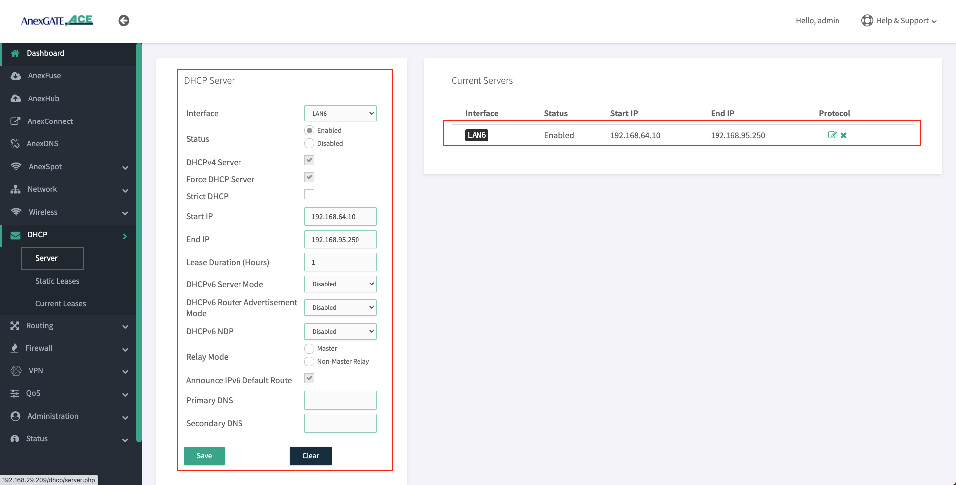
- AnexGATE router can have multiple LAN interfaces. The router can be configured with normal DHCP server where the Non-Hotspot user can issue an IP Address via LAN DHCP Server and access internet without any authentication or authorization.
To configure DHCP Server for Non-Hotspot LAN, Go toDHCP - Server. - Following are the parameters required to configure a DHCP server for Non-Hotspot LAN port.
|
Elements |
Description |
|---|---|
Interface |
Select appropriate LAN interface. |
Status |
Enable / Disable the LAN DHCP Server. |
DHCP v4 Server |
Select this to enable DHCP v4 Server to assign IPV4 addresses to endpoints. |
Force DHCP Server |
Forces DHCP serving on the specified LAN interface even if another DHCP server is detected on the same LAN network. |
Strict DHCP |
Select this to only assign IP addresses to endpoints which are added in DHCP - Static Lease. |
Start IP |
Assign beginning IP address from the DHCP pool for the specified network. |
End IP |
Assign ending IP address from the DHCP pool for the specified network. |
Lease Duration (Hours) |
Assign DHCP lease time for the endpoint connected to the specified network. The time starts from 1 hour. |
Primary/Secondary DNS |
Assign Primary/Secondary DNS servers (optional). |
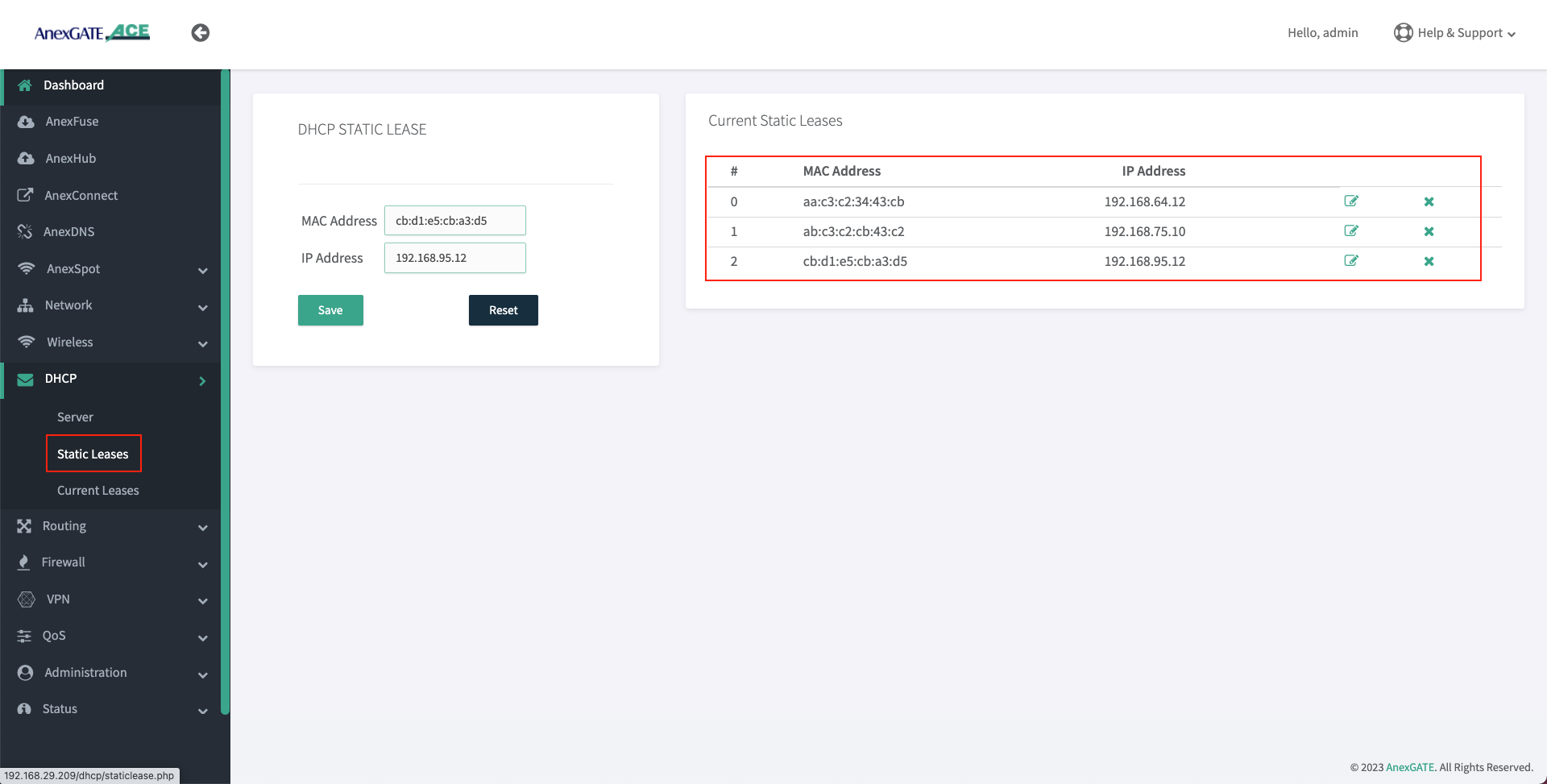
¶ Configure DHCP Static Lease
- To configure DHCP Static Lease for Non-Hotspot LAN network, Go to
DHCP - Static Lease. - Assign IP address to the MAC Address as shown in the image.
¶ DHCP Current Leases
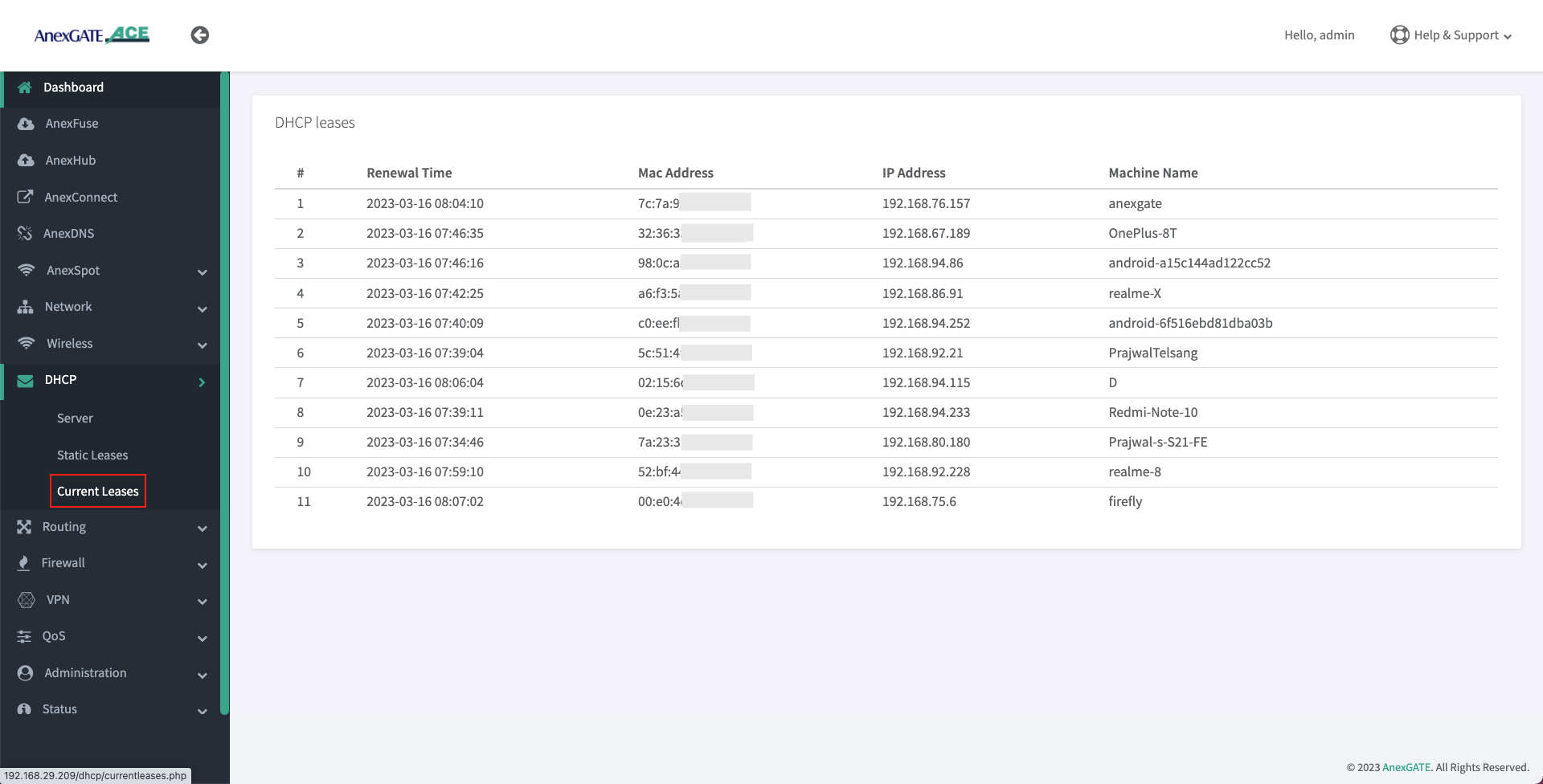
- DHCP Current Leases displays information such as IP Address, MAC Address and Hostnames of the endpoints which have been assigned IPs automatically via LAN DHCP Server (Non-Hotspot Network) as shown in the image below.
- To see the DHCP current leases, Go to
DHCP - Current Leases.
¶ Setting up WAN Interfaces
- AnexGATE router WAN interface can be configured in three ways. To configure WAN interface, Go to
Network - WAN/LAN
1. DHCP (Automatic IP assigned by the ISP Router)
2. Assigning Static IP Address with Gateway and DNS
3. PPPoE Dial Up on the AnexGATE ACE router.
NOTE:
- If configuring a
Single WAN link, do not assign any metric on a WAN link interface under Metric Field. - If there are
Multiple WAN links, metrics must be assigned to each WAN link interface to avoid network conflicts and configure Load Balancing.
WAN can also be configured as VLAN by selecting WAN as interface type and assigning VLAN ID. Make sure the configured LAN/WAN interfaces are added under Firewall Rules in order to get the login page.
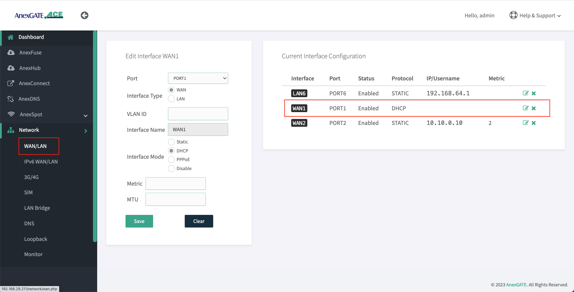
¶ Configure WAN as DHCP Client
To configure WAN for receiving IP via DHCP server from the upstream router, Go to Network - WAN/LAN.
- Select Port, Interface Type and select Interface Mode as DHCP.
- Assign metric to the interface if multiple wan links are being configured.
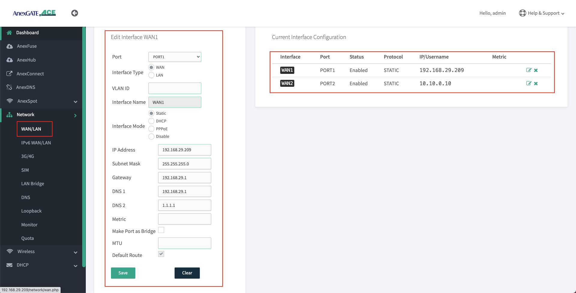
¶ Configure WAN as Static IP Address and DNS
To configure WAN as Static IP address, go to Network - WAN/LAN.
- Select Port, Interface Type and select Interface Mode as Static IP.
- Assign following parameters required for WAN configuration as shown in the image.
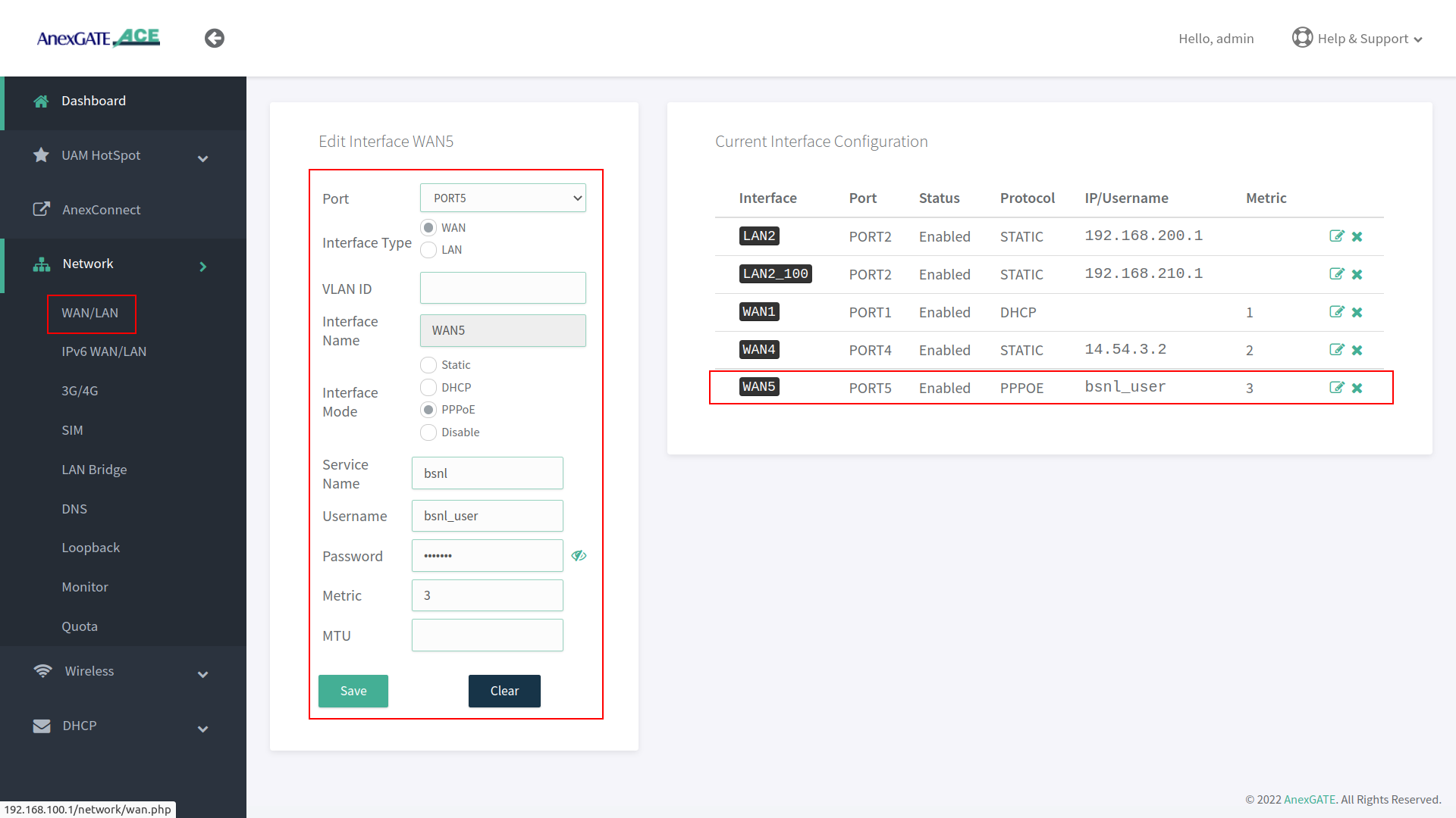
¶ Configure WAN as PPPoE Dial up
To configure WAN as PPPoE, go to Network - WAN/LAN.
- Select interface port, interface type as WAN, select Interface Mode as PPPoE.
- Assign PPPoE username and Password.
- Assign service name of the provider if necessary.
IMPORTANT NOTE:
Either remove 10.10.0.10 network configuration from the router at the end, after all necessary WAN / LAN and hotspot configuration is done or leave it as a backup port to access the router. If considering leaving it as a backup port access, assign metric 2 for it to not interfere with existing WAN network.
¶ Load Balancing and Bandwidth Aggregation
Load Balancing can be performed, if multiple links are being configured. The AnexGATE ACE Router supports 3 modes of Load Balancing.
- Bandwidth Aggregation
- Load Balance by Load Level
- Failover Load Balance by Priority
Balancing Interfaces has to be configured before setting up Load Balancing multiple links on the router.
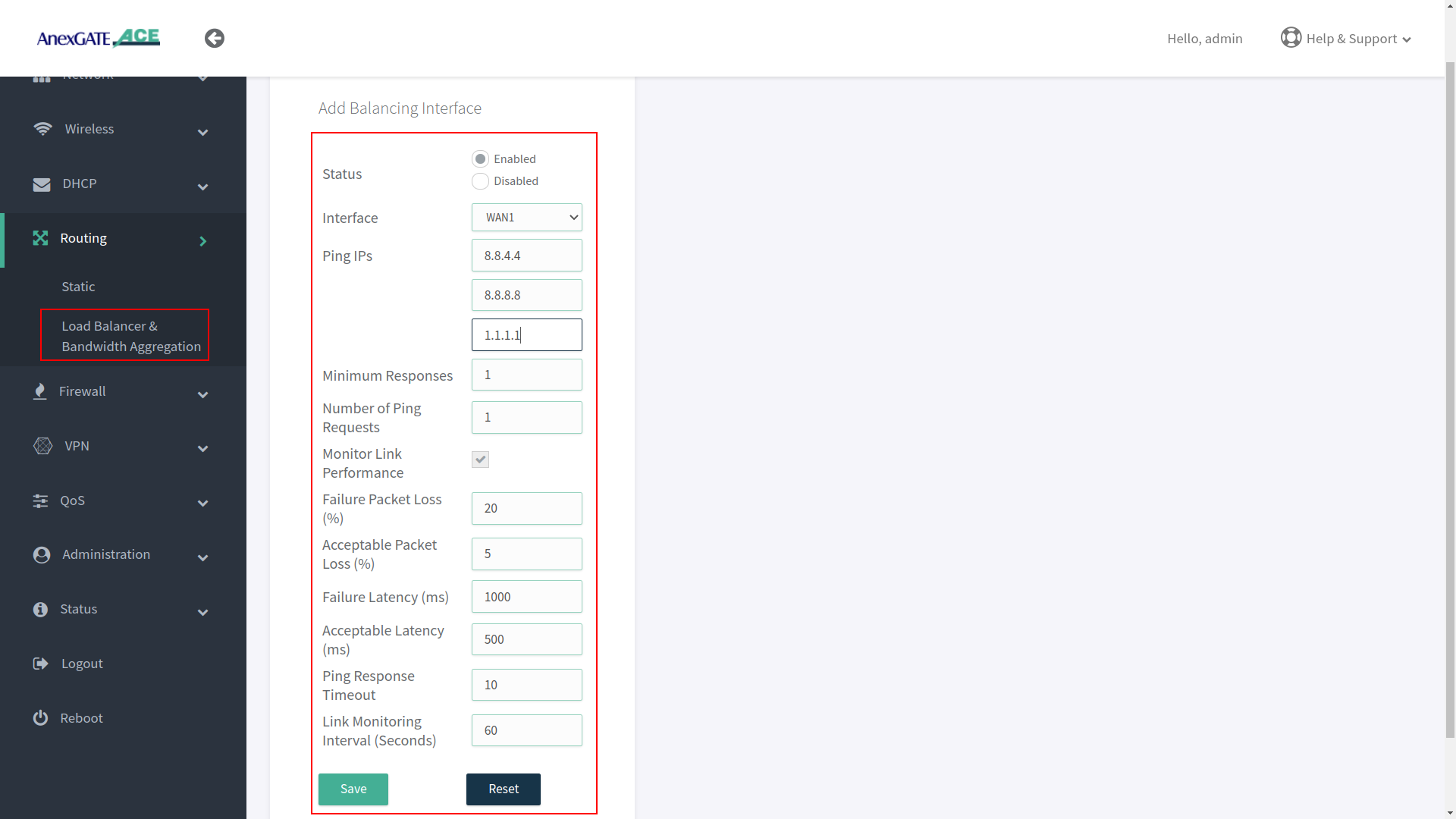
¶ Configuring Balancing Interfaces
WAN Interface/s must be added under Balancing interface in order to check the link status / reachability towards internet.
Following parameter values are added by default under Balancing interfaces.
| Element | Description |
|---|---|
Status |
Enable/Disable the configuration setting. Enable/Disable the configuration setting. |
Interface |
Select WAN interface to monitor Link Status. |
Ping IPs |
Assign Ping IPs to check if interface link status is still alive considering the reachability to them. |
Minimum Responses |
Number of Ping IPs that must reply for the link to be considered as successful. |
Number of Ping Requests |
Number of echo requests to send to each IP to check link status. |
Monitor Link Performance |
Enable this to check the overall link quality with packet loss and/or latency measurements. |
Failure Packet Loss (%) |
Maximum percentage of packet loss for a WAN link to be considered as DOWN when Monitor Link Performance is enabled. |
Acceptable Packet Loss (%) |
Minimum percentage of packet loss for a WAN link to be considered as UP when Monitor Link Performance is enabled. |
Failure Latency (ms) |
Maximum packet latency in milliseconds for a WAN link to be considered as DOWN when Monitor Link Performance is enabled. |
Acceptable Latency (ms) |
Minimum packet latency in milliseconds for a WAN link to be considered as UP when Monitor Link Performance is enabled. |
Ping Response Timeout |
Number of seconds to wait for ping response once a ping-request is sent from a WAN link before considering as lost. |
Link Monitoring Interval (seconds) |
Number of seconds between each Link Status check of WAN interfaces. |
NOTE:
- Initially, by default WAN interfaces are configured under Balancing and are in disabled state. Click on Add (+)/Edit and Enable the WAN link.
- While configuring Balancing interface
Performance Link Monitormust be enabled in order to receive the Latency report in AnexCONNECT portal. - Enable the WAN Link under Balancing even if it is a single WAN link and Enable Monitor Link Performance in order to receive telemetry status & Latency Report in AnexCONNECT portal.
¶ Load Balancing
Load Balancing has to be configured only when there are multiple WAN links being configured.
Following are the Load Balancing Techniques which can be configured in AnexGATE Router:
|
Elements |
Description |
|---|---|
Router Outgoing Interface |
Working LAN Interface needs to be selected. Default = lan_br0. |
Import Routes from Table |
Import routes from specific IP rule list. Default = None. |
| Modes | |
Bandwidth Aggregation |
Multiple WAN Links configured are in Active-Active State where LAN systems can initiate TCP connection/session on any of the configured multiple WAN Link. |
Load Balance by Load Level |
Inbound/outbound Traffic flow can be configured on WAN links in terms of percentage which must be equal to 100. Example: WAN1 = 70% - Most of the traffic will flow through link WAN 1. WAN2 = 30% - Less traffic is directed over WAN 2 link. |
Failover Load Balance by Priority |
WAN Traffic will be initially flowing on WAN link with “Priority 1” as primary.
|
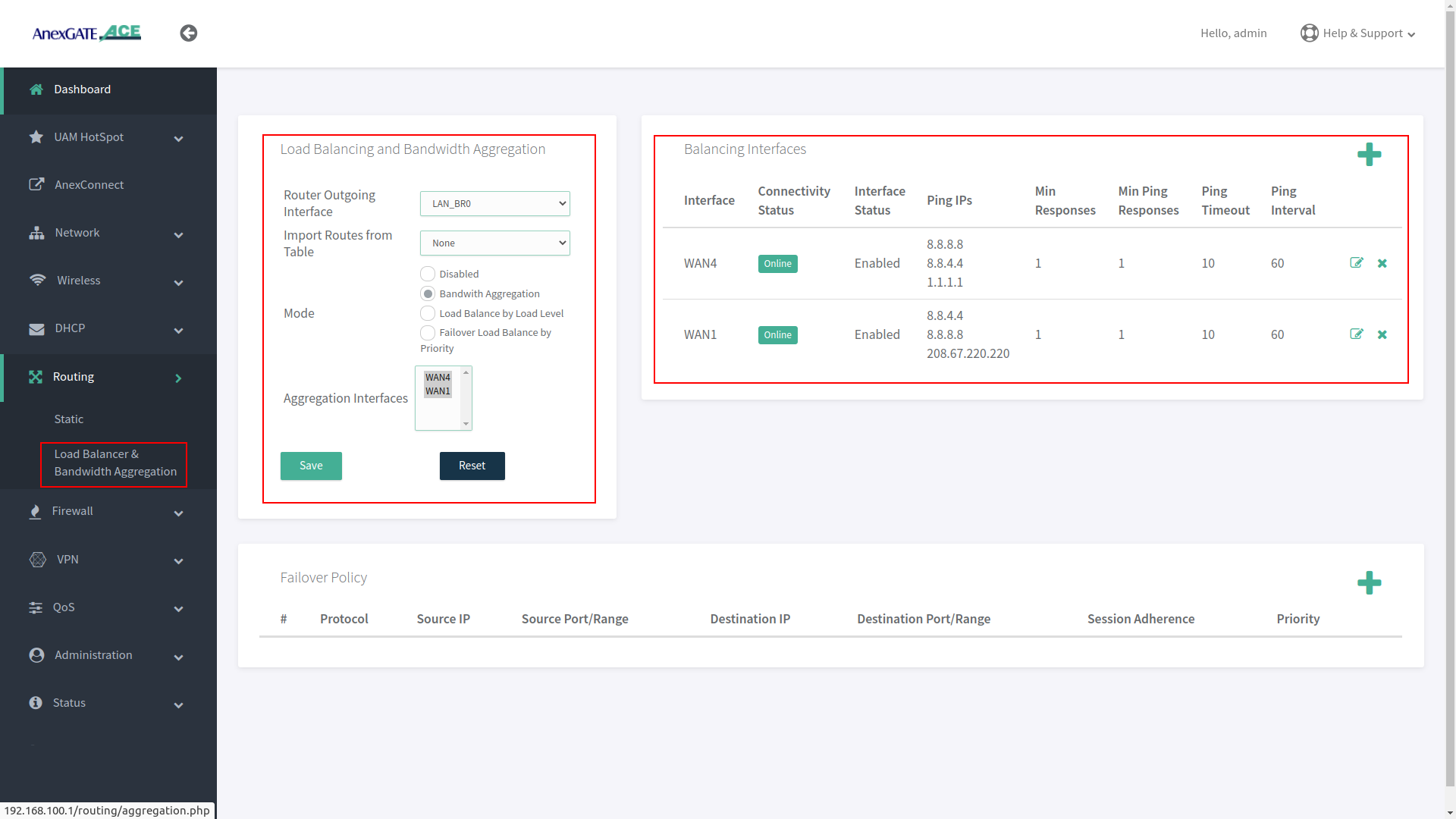
¶ Bandwidth Aggregation
Under Bandwidth Aggregation, both the links are in Active - Active state where TCP sessions/connections are established on one or other WAN port randomly.
If one link goes down the other links will act as a backup. If any TCP connection has been established on a link and that link goes offline, reload the browser to establish TCP session/connection on other link or start another ping session if testing.
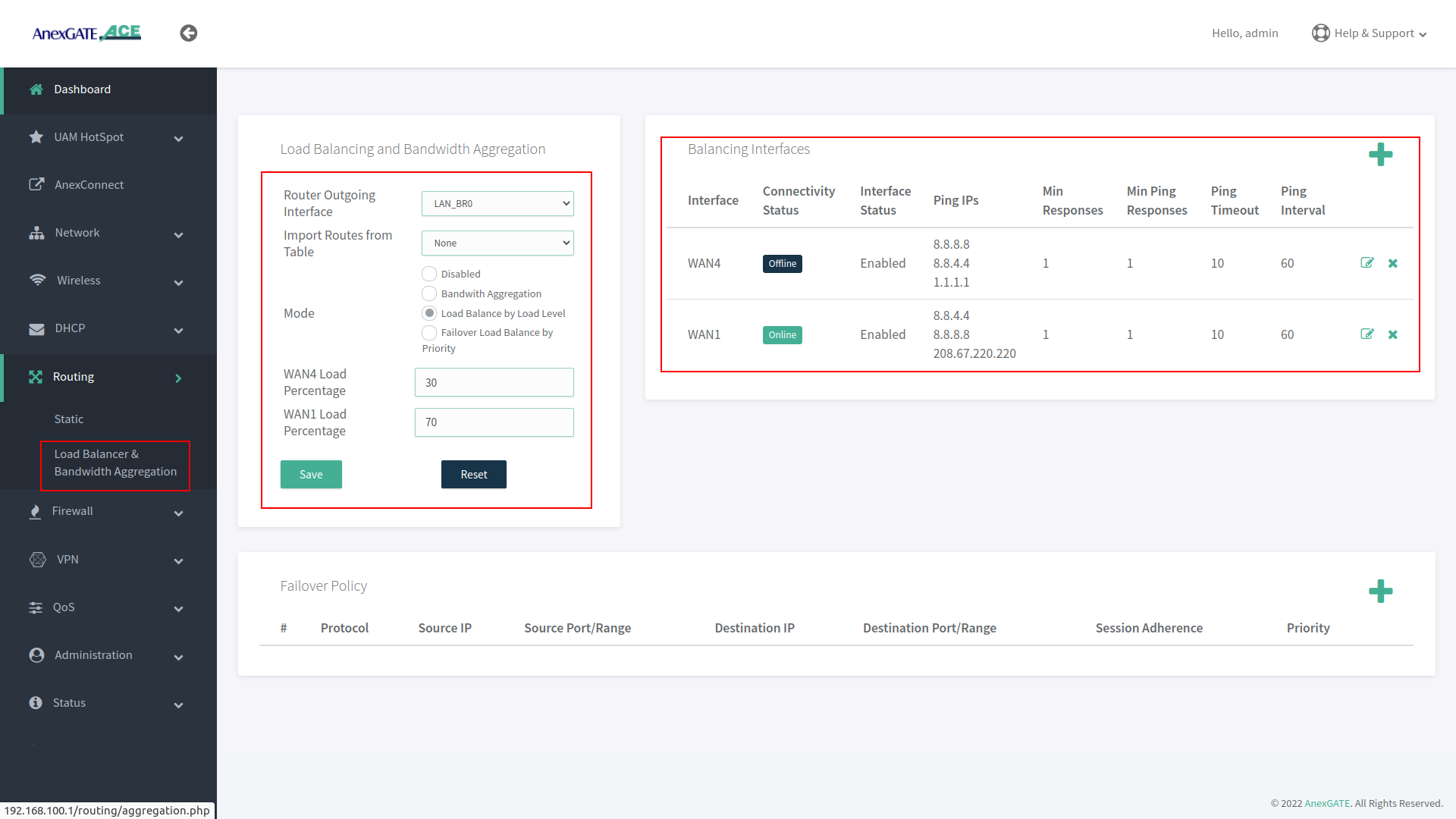
¶ Load Balance by Load Level
Under Load Balance by Load Level, Both the links can be configured as per basis of weight. As shown in the image, WAN 1 is configured to handle 70 percent of traffic load flow through the link and WAN 2 is configured to handle 30 percent of traffic load flow.
If one of multiple WAN links goes down or offline, whole traffic load will be shifted to secondary link.
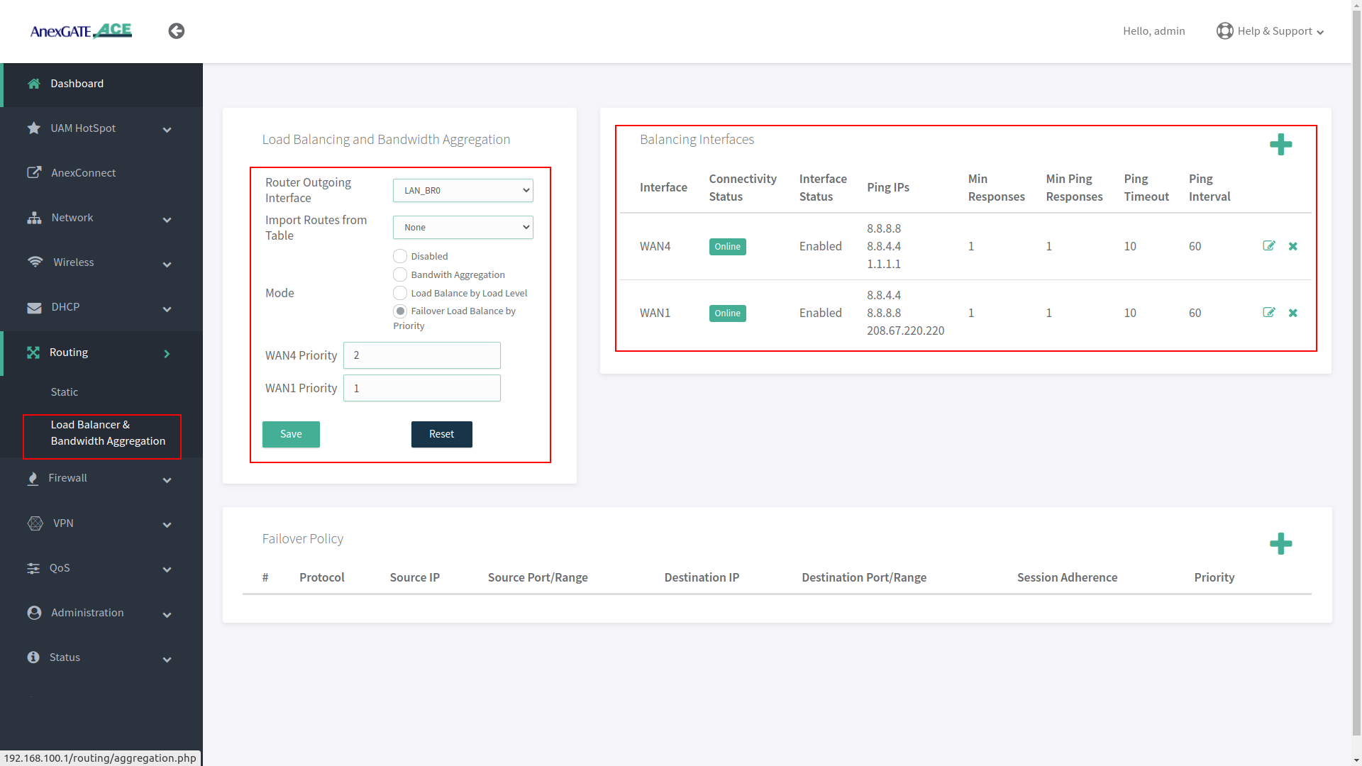
¶ Failover Load Balance by Priority
Under Failover Load Balance by Priority, WAN links are in Active - Passive state where Low Priority metric (1) takes precedence and become primary over other configured WAN links.
Initially, all the traffic flow will be on Primary Link with low metric priority. If the Primary link fails to reach/ping IPs per basis conditions applied in Balancing Interfaces, it will failover to secondary link according to the priority metric assigned. This usually takes a minute to failover to secondary link. This can be adjusted under Balancing Interfaces as per parameters mentioned above.
If the Primary link comes online, the secondary link will switch and get rolled over to primary link without any interruption in the local network.
¶ Setting up the Firewall
The firewall configuration is fairly straight forward and automatically provides the router with a base rule set of rules and an understandable configuration file for additional rules.
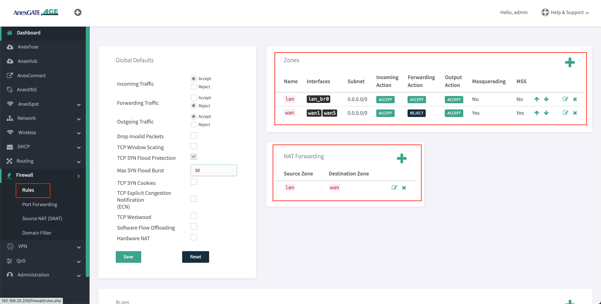
¶ Firewall Zone
To configure a Firewall Zone, Go to Firewall - Zones.
- A
firewall zonegroups one or more interfaces under a zone and serves as a source or destination for traffic forwarding. - To configure Multiple WAN/LAN Interfaces under Firewall Zones, select and edit “WAN” Zone, and add configured WAN Interfaces (WAN1 and WAN2 are added in the WAN Zone by default).
- ADD or EDIT
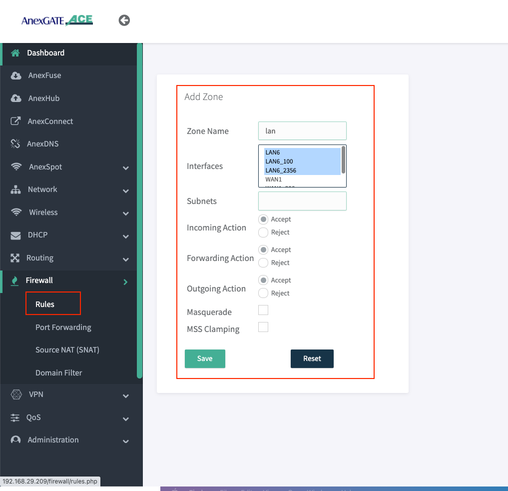
LANWANHSPTIPSECzone and select multiple interfaces to add by pressingCtrlbutton and click on the interface (WAN1, WAN2, WAN3, USB0) as per requirement as shown in the image below.
¶ Assigning Interfaces in LAN ZONE
- Press Ctrl and hold to select multiple interfaces.
- Select Incoming, Forwarding and Outgoing as ACCEPT.
- Do not select Masquerade and MSS Clamping while assigning LAN interfaces.
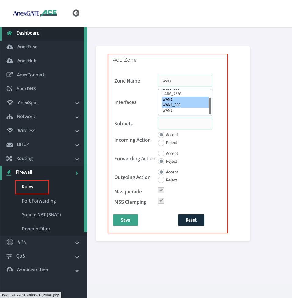
¶ Assigning Interfaces in WAN ZONE
- Press Ctrl and hold to select multiple interfaces.
- Select Incoming and Outgoing Action as ACCEPT and Forwarding Action must be in REJECT state.
- Select Masquerade and MSS Clamping while assigning WAN interfaces.
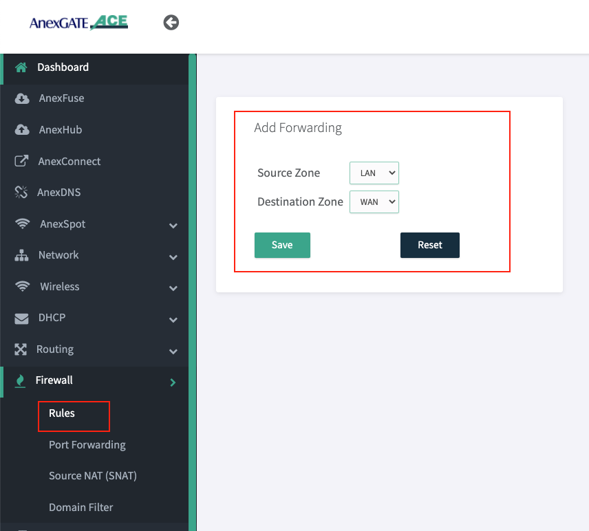
¶ NAT Forwarding
NAT Fowarding controls the traffic flow between zones. Under NAT Fowarding, click on + icon.
By default, the NAT Forwarding is done on following zones.
- Source Zone:
lanDestination Zone:wan
NOTE:
- After configuring LAN/vLAN or WAN interfaces, make sure to add the interfaces under their respective Firewall Zones. If not properly configured, the access login page will not appear when connected to LAN.
- Create IPSec Zone and add remote subnet without selecting any interfaces and all Firewall actions will be in ACCEPT condition.
- For IPSec, NAT Forwarding must be configured as follows:
Source Zone: lan Destination Zone: ipsec
Source Zone: ipsec Destination Zone: lan
- Similarly, for the multiple LAN interfaces added in different zones. If there is necessity to forward traffic from one zone to another zone for network reachability then NAT Forwarding between those two zone must be configured.
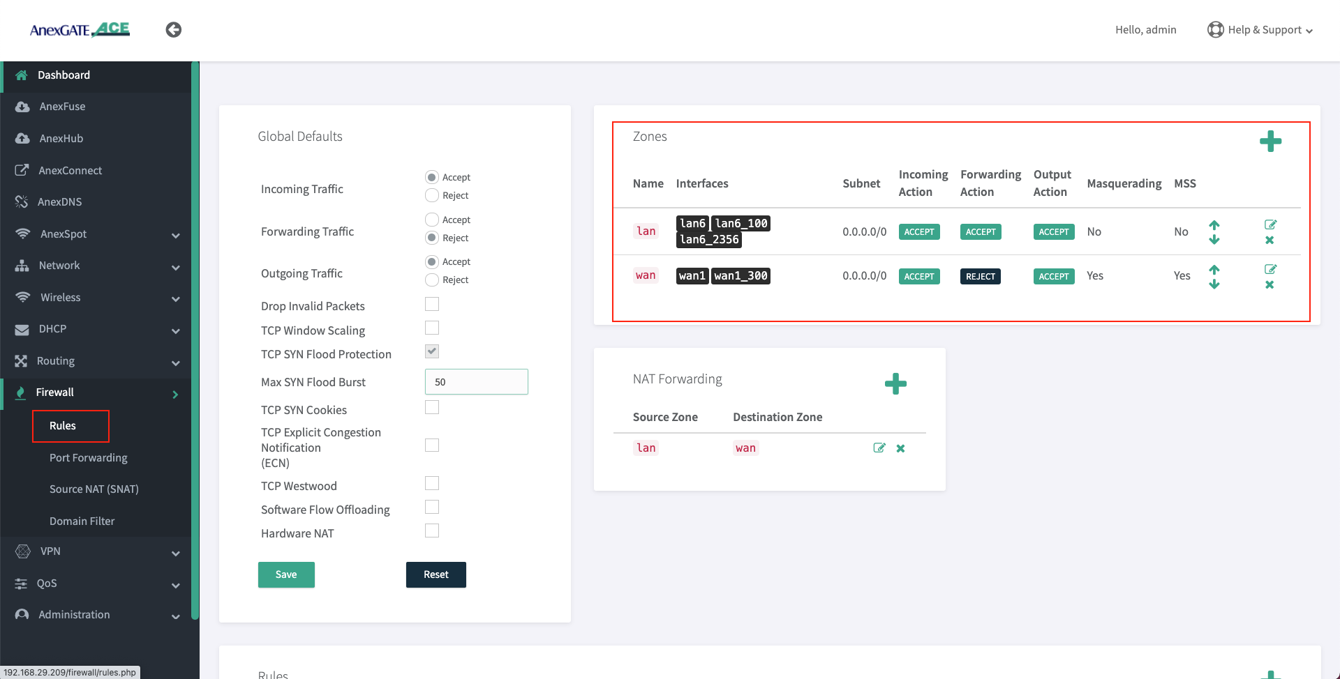
¶ Firewall rules after Assigning Interfaces into the Firewall Zones
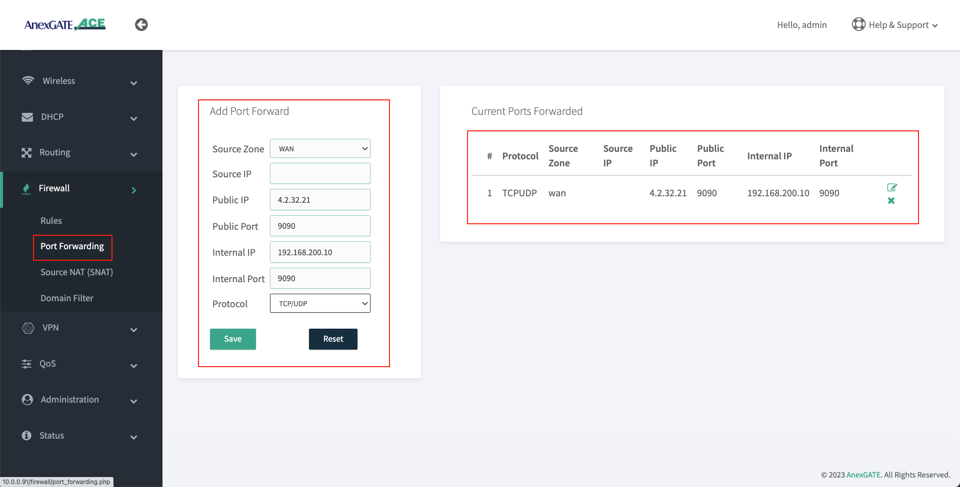
¶ Port Forwarding
Port Forwarding directs AnexGATE router to send any incoming data from the internet to a specified device on LAN network.
To configure Port Forwarding rule, Go to Firewall - Port Forwarding.
|
Elements |
Description |
|---|---|
|
|
Select the WAN Zone as a Source to listen to the incoming connections. |
|
|
Assign Source IP to only get port forward the request from source IP address. |
|
|
Enter Public IP configured on the Router to port forwards requests to internal (LAN) IP. |
|
|
Enter Public Port to accept WAN requests to be port forwarded only for that specific port. |
|
|
Enter LAN IP Address for WAN requests to be redirected towards internal (LAN) IP. |
|
|
Enter Internal Port that is listening to requests on the mentioned internal (LAN) IP. |
|
|
Specify TCP, UDP or both TCP/UDP protocols. |
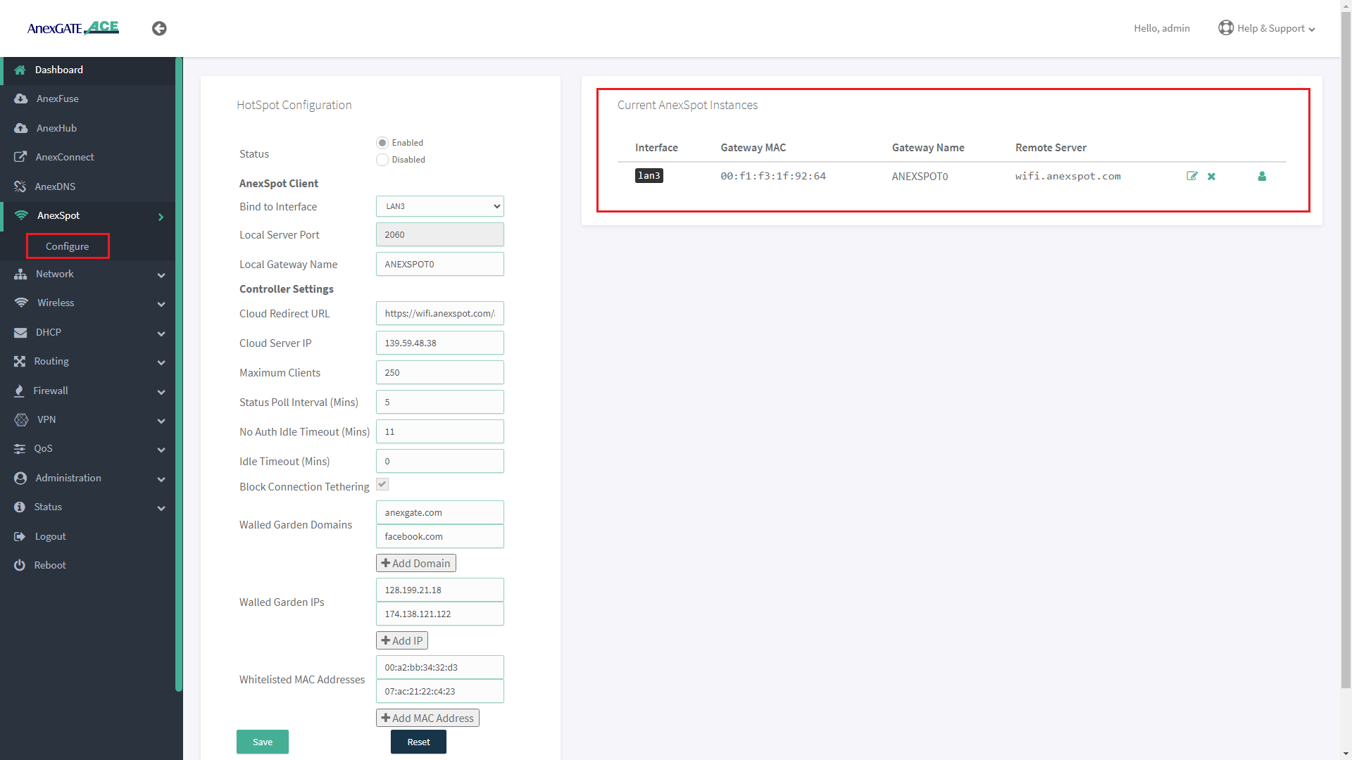
¶ ANEXSPOT
¶ AnexSPOT CONFIGURATION
|
Elements |
Description |
|---|---|
Status |
Enable or Disable the AnexSPOT feature. |
| AnexSPOT Client | |
Bind to Interface |
Select the LAN Gateway Interface on which the AnexSPOT feature has to be enabled. E.g.: LAN2 Port has been selected in the image. NOTE: Lan Bridge must not be used to configure AnexSPOT. |
Local Server Port |
Local Gateway server port will be assigned automatically. E.g.: Port 2060 has been assigned as the LAN Gateway server Port. |
Local Gateway Name |
Assign Local Gateway Name for the AnexSPOT instance being configured. |
| Controller Settings | |
Cloud Redirect URL |
Specify Cloud Redirect URL and path of the Authentication Server to forward the Authentication requests. E.g.: https://wifi.anexspot.com/auth |
Cloud Server IP |
Specify Cloud Server IP of the Authentication Server to which the Authentication requests are forwarded. |
Maximum Clients |
Specify Maximum Number of clients that can be connected to AnexSPOT. E.g.: 100 |
Status Poll Interval |
Specify the time interval in minutes at which AnexSPOT will check for new connected clients, quota usage and handle Expired Sessions. Minimum Status Poll Interval assignment begins from 5 minutes. E.g.: 5 NOTE: The Status Poll interval (set in seconds) must not exceed half the duration set for No Auth Idle Timeout (set in minutes). |
No Auth Idle Timeout (Mins) |
Specify the timeout interval in minutes after which an idle device that is not yet authenticated and is still in Pre Authentication state, its connection will be terminated. Minimum No Auth Idle Timeout assignment begins from 11 minutes. Eg: 20 |
Idle Timeout (Mins) |
Specify the time after which the Authenticated Device connection will be de-authenticated and logged out due to inactivity. Eg: 60 |
Block Connection Tethering |
Enable this option to block the Authenticated user from sharing Internet from his Mobile or Laptop Personal Hotspot to other network devices. |
Walled Garden Domains |
Add domain name that are to be whitelisted and can be accessed without authentication required. This field is optional. |
Walled Garden IPs |
Add IP addresses that are to be whitelisted and can be accessed without authentication required. This field is optional. |
Whitelisted MAC Addresses |
Add MAC Address of the devices that are to be whitelisted from the AnexSPOT and get internet access directly without authentication. |
SAVE |
Save the AnexSPOT configuration Settings. |
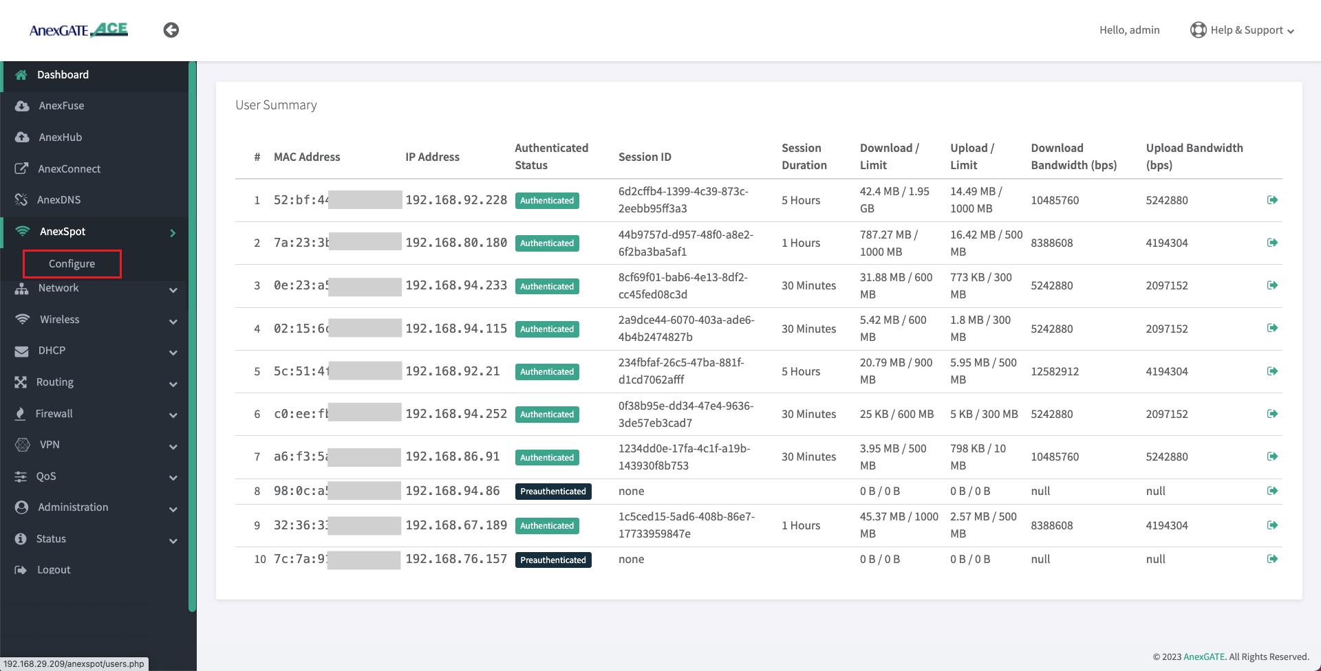
¶ AnexSPOT USERS
- Users and client devices connected under ACE AnexSPOT will be displayed under AnexSPOT. To view the users, Go to
AnexSPOT - Configure. - Click on the Users icon at the end of the AnexSPOT gateway instance displayed under Current AnexSPOT instances table as shown in the image below.
- AnexSPOT User Summary displays the client information that is connected to the AnexSPOT network such as follows:
| Element | Description |
|---|---|
MAC Address |
Client's Mac address will be displayed who gets connected to the AnexSPOT Server. |
IP Address |
Client's IP Address will be displayed assigned by the ACE DHCP Server. |
Authenticated Status |
Preauthenticated/Authenticated state is displayed for the clients connected to AnexSPOT Server.
|
Session ID |
Session ID will be assigned by the AnexSPOT server after the client has been Authenticated. |
Session Duration |
Client's Session Duration assigned by the AnexSPOT Server. Once the session duration finishes, the client gets de-authenticated and looses Internet access. |
Download Limit |
Displays Client's Download Quota Limit. Once the quota limit is surpassed, the client gets de-authenticated, once the information from ACE router is sent to AnexSPOT cloud server. |
Upload Limit |
Displays Client's Upload Quota Limit. Once the quota limit is surpassed, the client gets de-authenticated, once the information from ACE router is sent to AnexSPOT cloud server. |
Download Bandwidth (bps) |
Displays Download Rate Limit assigned to the client by the AnexSPOT server. |
Upload Bandwidth (bps) |
Displays Upload Bandwidth rate Limit assigned to the client by the AnexSPOT server. |
Logout |
Click on the Logout icon to force logout the already authenticated clients. |
¶ AnexSPOT User Summary
- Click on the
Usericon underAnexSPOT - Configure- Current Instances table as shown in the image above. It will direct to the Users that are connected to AnexSPOT network.
NOTE:
1. Do not configure AnexSPOT on LAN_br0 interface.
2. The LAN port link must be up and connected to the device (Laptop/Router) before saving the AnexSPOT Settings.
3. Delete Bridge Interfaces (Eg: lan_br0) if any, to have a working AnexSPOT on a LAN interface that is configured under Network - WAN/LAN on a single port and is not a part of bridge configuration.
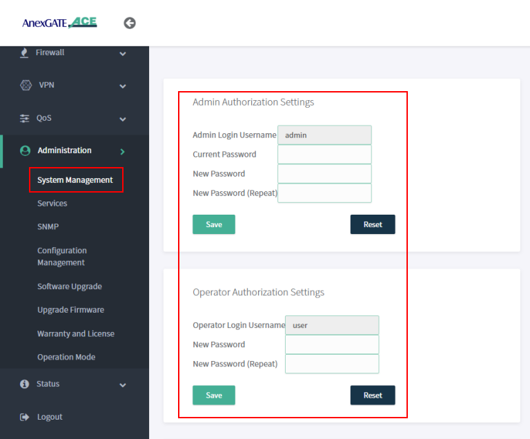
¶ Administration, System Management, Services and Syslog Settings.
¶ Admin and User Login
Under System Management, Admin and User password can be changed by entering the current default password and updating to new password accordingly.
NOTE:
Operator/User mode can be used for monitoring and diagnosis of the network and router. When using this credential, if any changes are being done the user will logout immediately without reflecting any changes in the router.
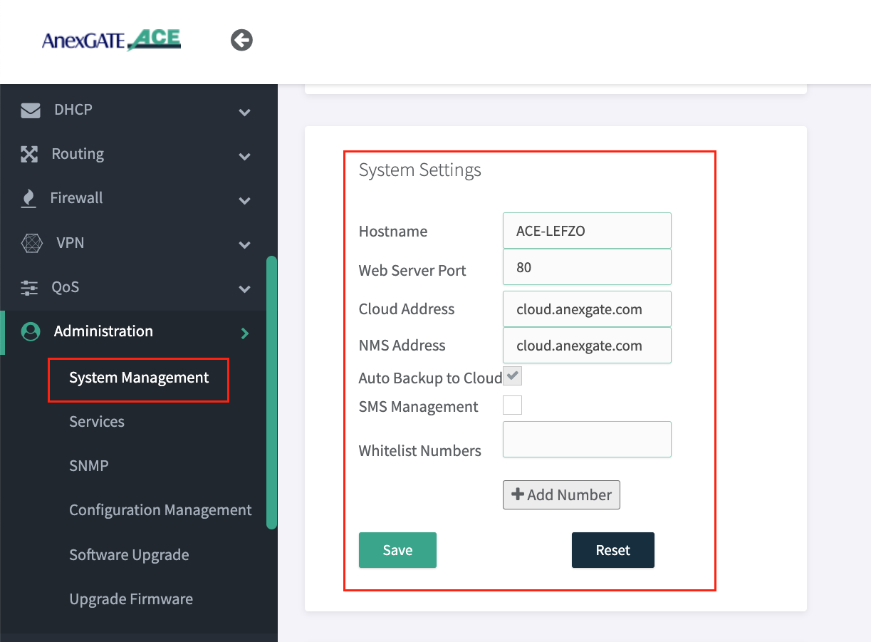
¶ Dashboard Access via WAN
Under Administration - System Management - System Settings , The Hostname and Web Server Port of the ACE router to recognize and access the router accordingly.
NOTE:
- Go to
Administration - Serviceand Restart WEBGUI Service after changing Dashboard Port. - Change NMS Address as
connect.anexgate.comfor enabling AnexCONNECT feature. (Paid Subscription required)
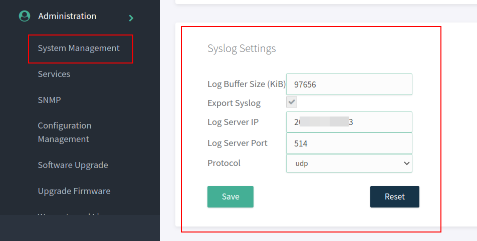
¶ Syslog Settings
Syslog must be configured in the ACE Hotspot router in order to receive device logs as well as NAT Logs of connected users to UAM hotspot.
To configure syslog settings,
Go to Administration - System Management - Syslog Settings in order to export the logs to the mentioned Public IP address and port.
NOTE:
The log buffer Size for USG model and ACE model is as follows:
- USG Series Model = 97656 KiB
- ACE Classic Plus Gigabit V2 = 4888 KiB
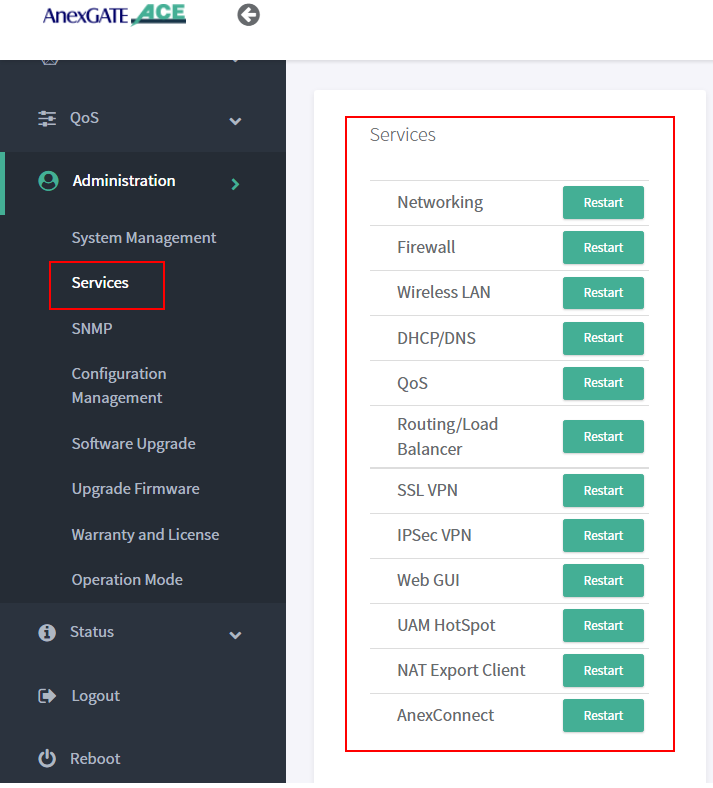
¶ AnexGATE Router Services
Under Administration - Services, each service running on the AnexGATE HotSpot router can be restarted without rebooting the device if a particular service is not functioning properly.
Also, it is useful when you do any changes in the router. It is recommended to restart the UAM Hotspot service for it to function as expected.
Services used for AnexGATE HotSpot are as follows:
| Service | Description |
|---|---|
Networking |
Restart LAN/WAN Service. |
Firewall |
Restart Firewall Services like Zone, Rules and NAT Forward. |
Wireless LAN |
Restart Wireless LAN Service. |
Routing/Load Balance |
Restart Load Balancing Service. |
SSL VPN |
Restart SSL VPN Tunnel Service. |
IPSec VPN |
Restart IPSec Tunnel Service. |
Web GUI |
Restart Dashboard Service. |
UAM Hotspot |
Restart UAM HotSpot Service. |
NAT Export Client |
Restart UAM Export Service. |
AnexConnect |
Restart AnexCONNECT Service. |
¶ Checking Network Status and Logs
Network Status and Logs allows the user to carry out Diagnostic operations over the AnexGATE Router.
The Diagnostic tools are as follows:
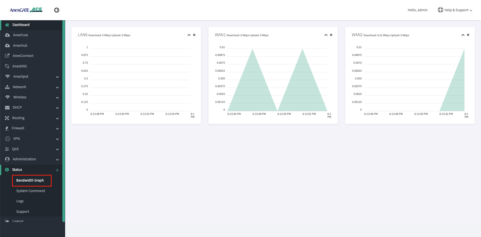
¶ Bandwidth Graph
Bandwidth Graph displays a live graphical Representation of the traffic flowing through the Interfaces configured on the ACE Router. It displays the graph of Inbound/Outbound Traffic on each Interfaces.
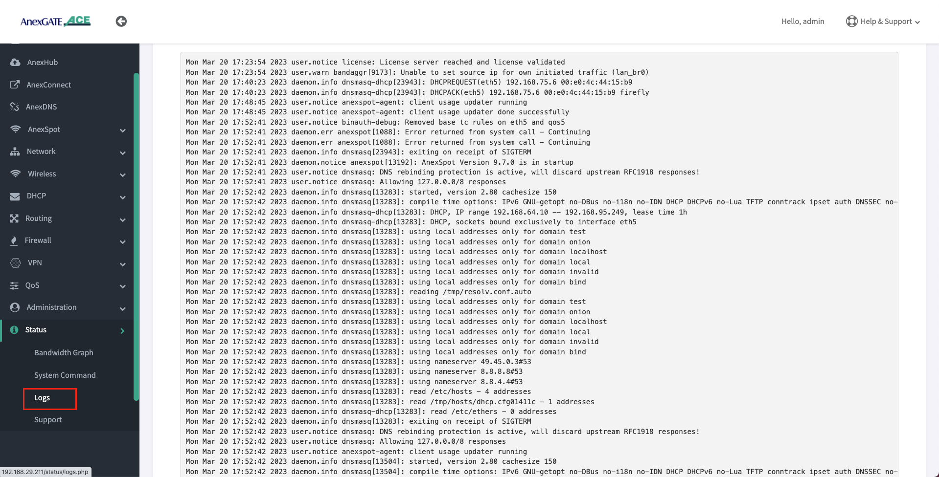
¶ Logs
Device or System Logs can be viewed at Status - Logs. The logs are stored temporarily and rotate as per Log buffer size assigned to the router.
NOTE:
All logs will be cleared after device reboot.
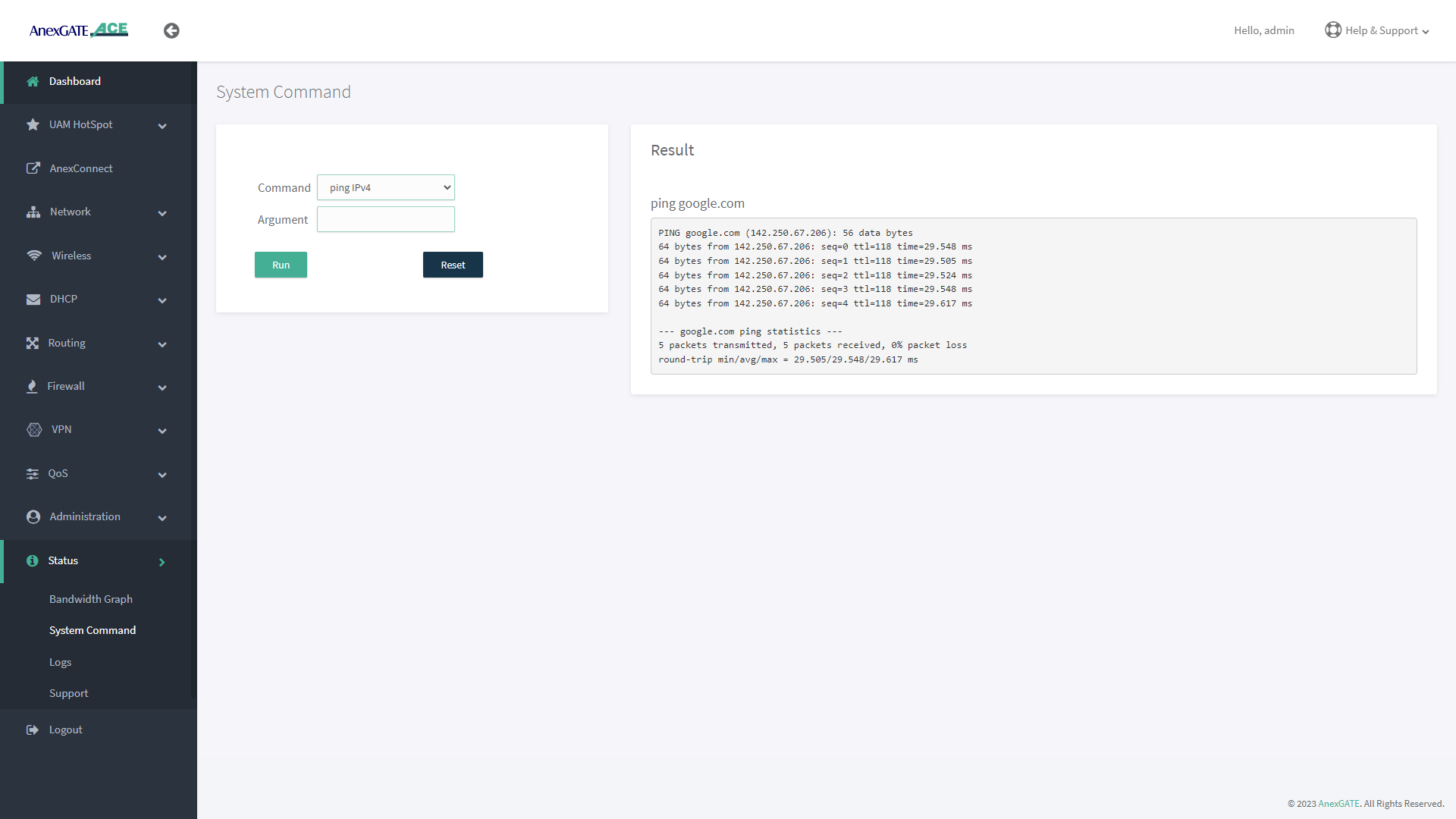
¶ System Command
System command are set of Commands useful for diagnosing the AnexGATE Hotspot Router, as well as troubleshooting the connectivity problems.
| Command | Argument | Description |
|---|---|---|
ping ipv4 |
<domain / ip address> Ex: Ex: |
Checks the reachability to the Domain or IP. |
|
<domain / ip address> -I <interface> Ex: Ex: |
Checks the reachability to the Domain or IP address on a particular interface. Interface = eth1, eth2, eth3 eth0.2, eth0.3 ( Interfaces for ACE Classic Plus Giga)etc.. |
|
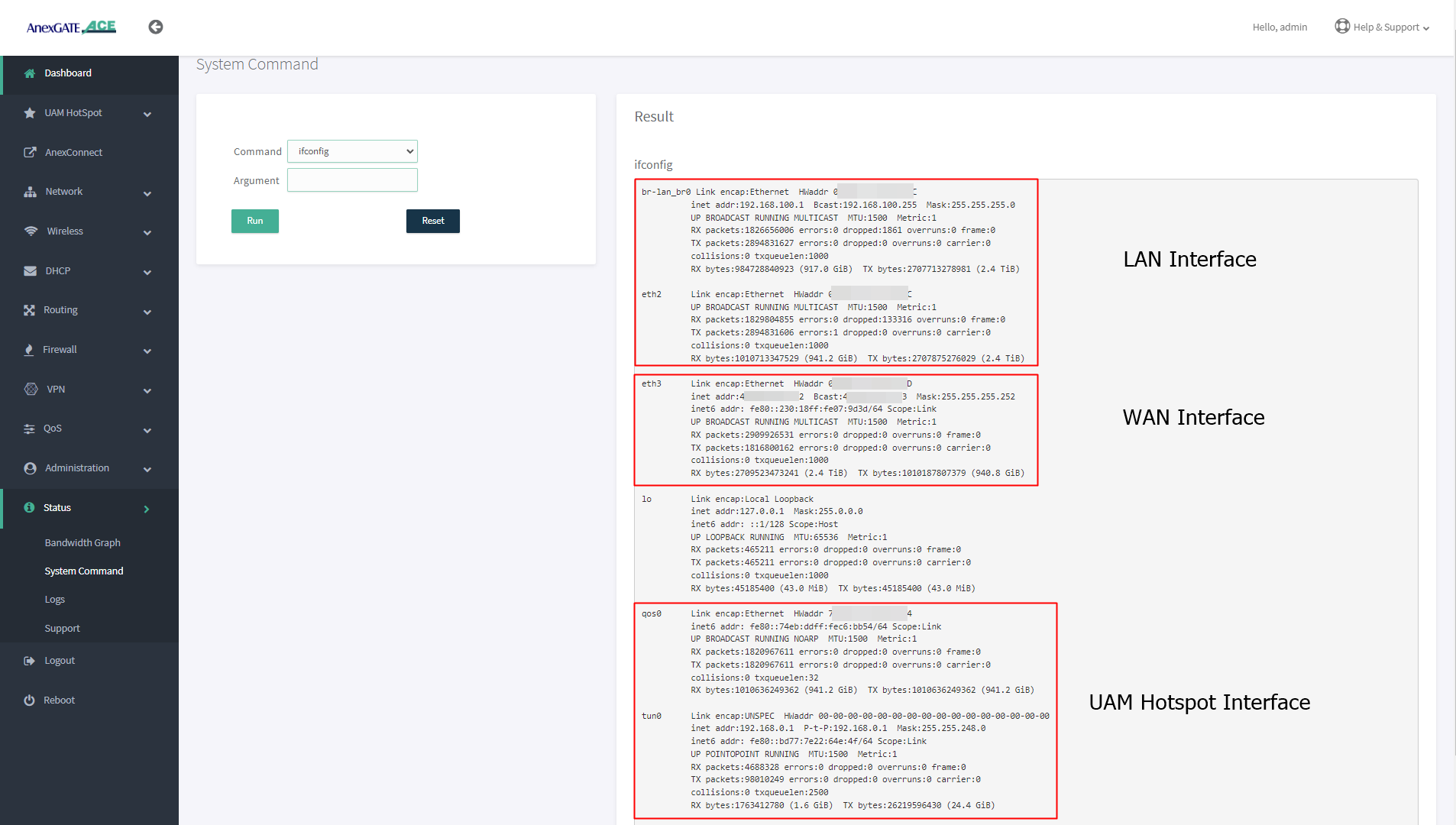
ifconfig |
**no argument** | Displays ‘active’ interface configuration. |
| -a | Displays interface configuration along with ‘inactive’ interfaces. | |
lsusb |
**no argument** | Displays information about USB buses in the system and the devices connected to them. |
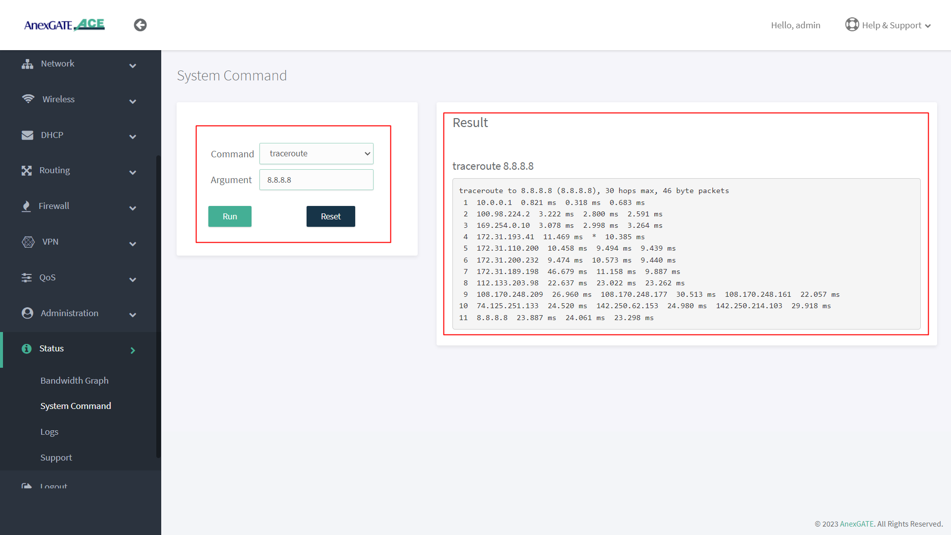
traceroute |
<domain or ip address> Ex: Ex: |
Displays the route that a packet takes to reach the host. Useful, when you want to know about the route and about all the hops that a packet takes. |
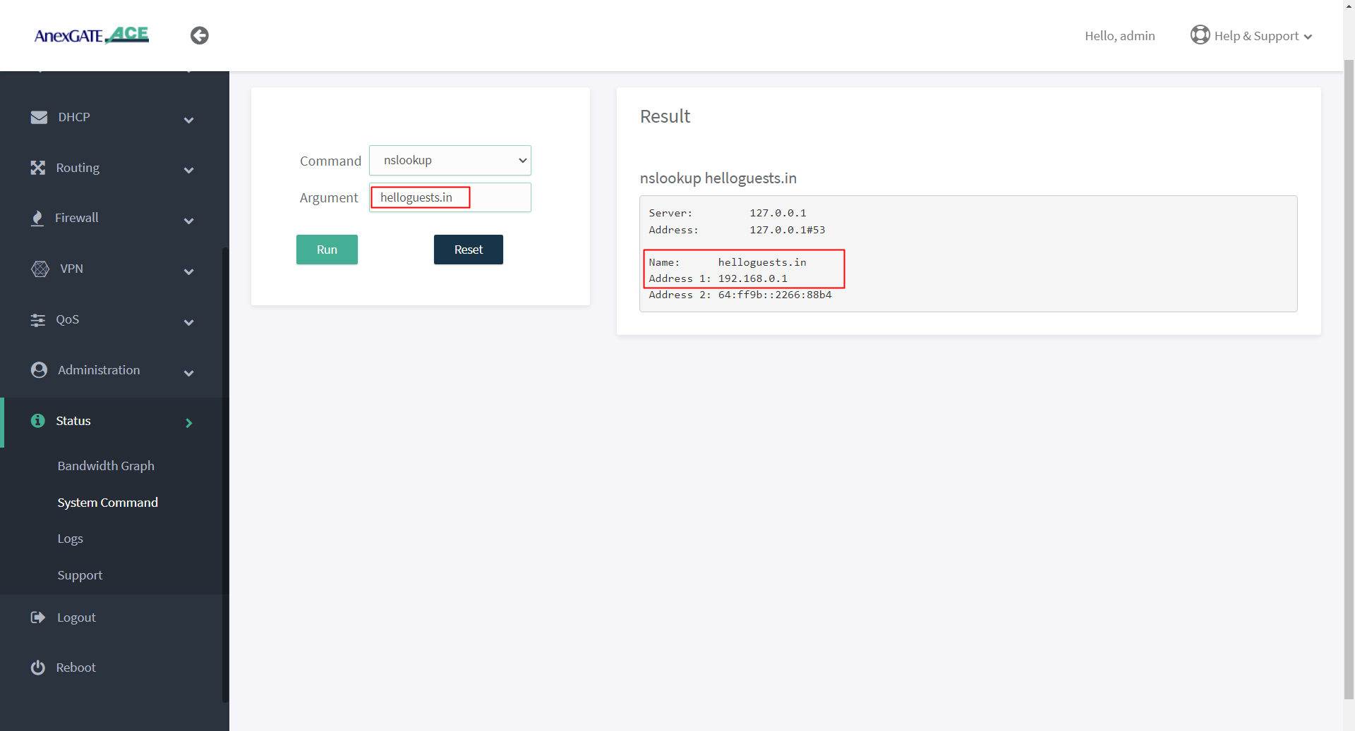
nslookup |
<domain or ip address> Ex: Ex: |
Displays “A record” (IP Address) of the domain and vice-versa. Use this command to find the address record for a domain. It queries to domain name servers and get the details. |
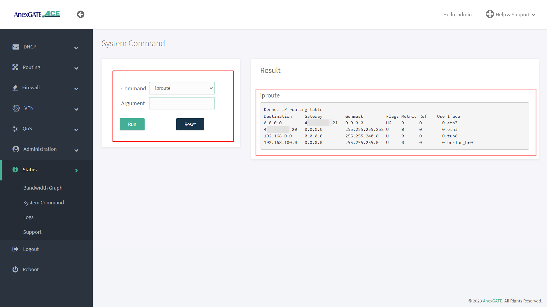
ip route |
**no argument** | Displays IP routing table. |
ipsec status |
**no argument** | Displays detail verbose output the IPSec Tunnel connectivity status. |
¶ PING Output
¶ IFCONFIG Output
¶ TRACEROUTE Output
¶ NSLOOKUP Output
¶ IP ROUTE Output
¶ Troubleshooting AnexGATE ACE Router
| Problem | Troubleshooting |
|---|---|
| Not able to ping or access the AnexGATE Router Dashboard |
OR
|
| LAN/WAN Connectivity Issues |
|
| Multiple WAN Links Configured but no Internet when pinged |
|
| Unable to get DHCP IP or ping Hotspot gateway on configured VLAN |
|