¶ Quickstart
¶ AnexGATE Router Ports Overview
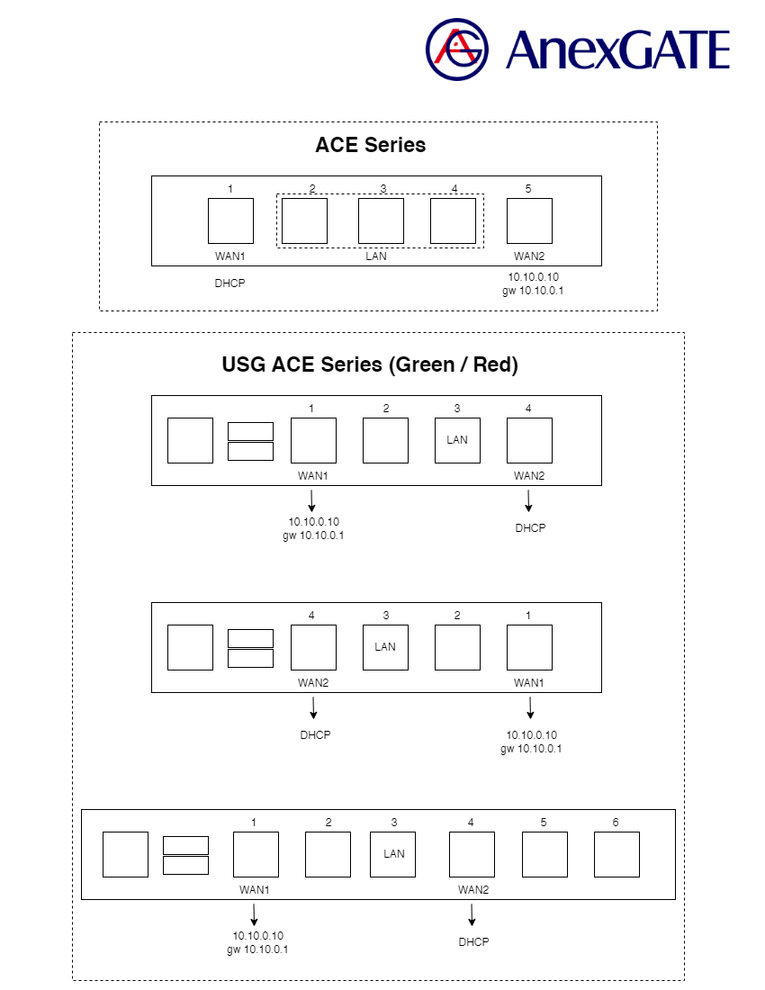
¶ AnexGATE Router Setup
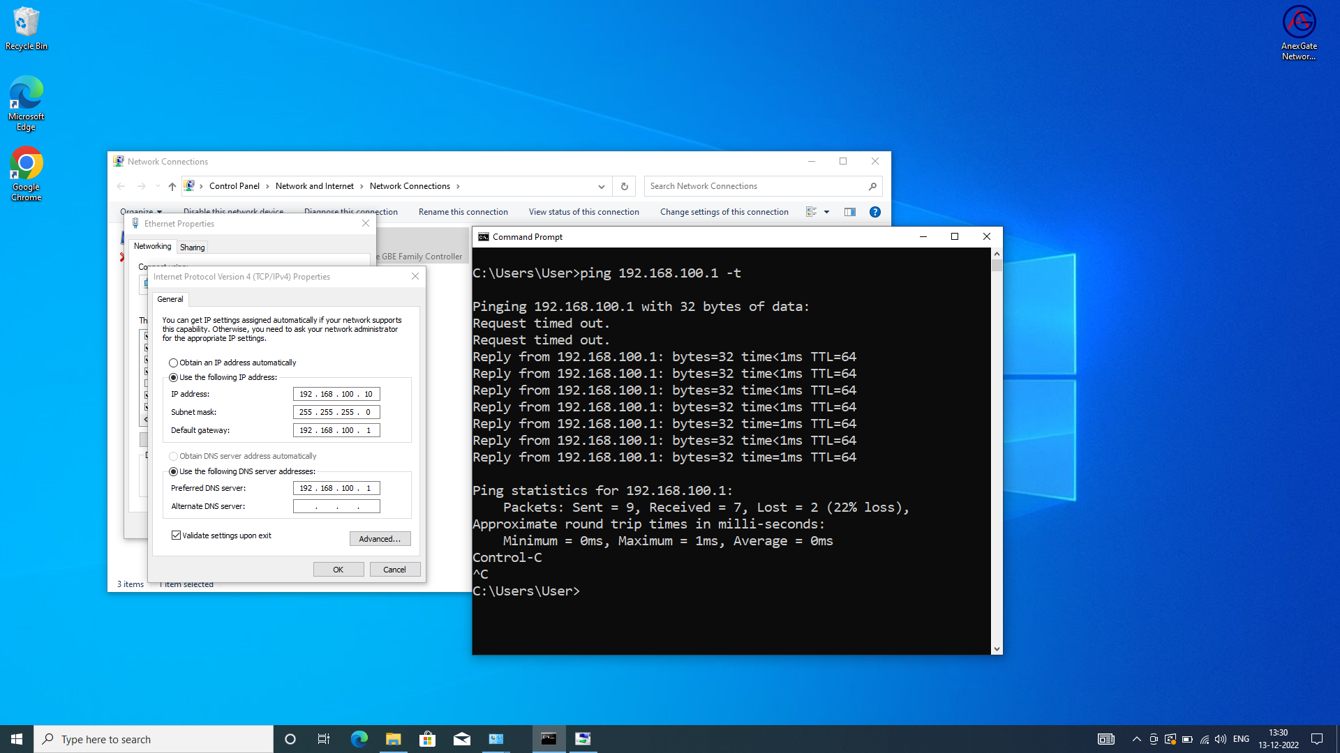
- Set a static IP Address to the System-PC.
IP Address = 192.168.100.10
Subnet Mask = 255.255.255.0
Gateway = 192.168.100.1
- Open Command prompt and type
ping 192.168.100.1 -tand start the ACE router. - Put network cable into LAN port and connect to System-PC.
- After successful ping to 192.168.100.1, Login to the router via Browser.
NOTE:
- The LAN cable must be connected to Laptop beforehand if the UAM Hotspot is already enabled. If failed to do so, reboot the device once in order to get the access of the router when trying to access by assigning physical LAN port IP (Example: 192.168.100.1).
- Alternatively, the router can also be accessed by connecting to the WAN Port i.e., 10.10.0.10 Static WAN IP which is configured on the router by default.
Connect the network cable to the port where Static WAN 10.10.0.10 is configured on the router.
Assign IP Address details to the Laptop as following:
-
Laptop IP Address- 10.10.0.1 -
Subnet Mask- 255.255.255.0 -
Gateway- 10.10.0.10
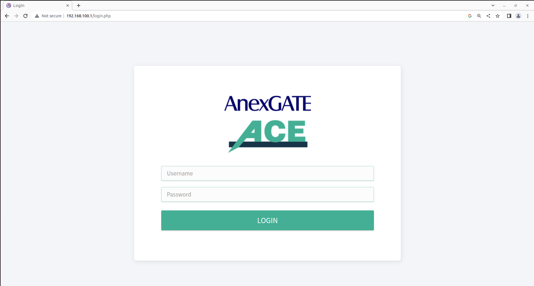
¶ LOGIN
Connect to the default LAN Port on the router, Open Internet Browser and type default LAN IP assigned to the router i.e., http://192.168.100.1
OR
Connect to the default static WAN Port on the router, Open Internet Browser and type the default WAN IP assigned to the router i.e., http://10.10.0.10
The default login credentials are mentioned below the ACE UAM HOTSPOT router.
NOTE:
Change the default password to avoid un-authorized logins to the AnexGATE Router.
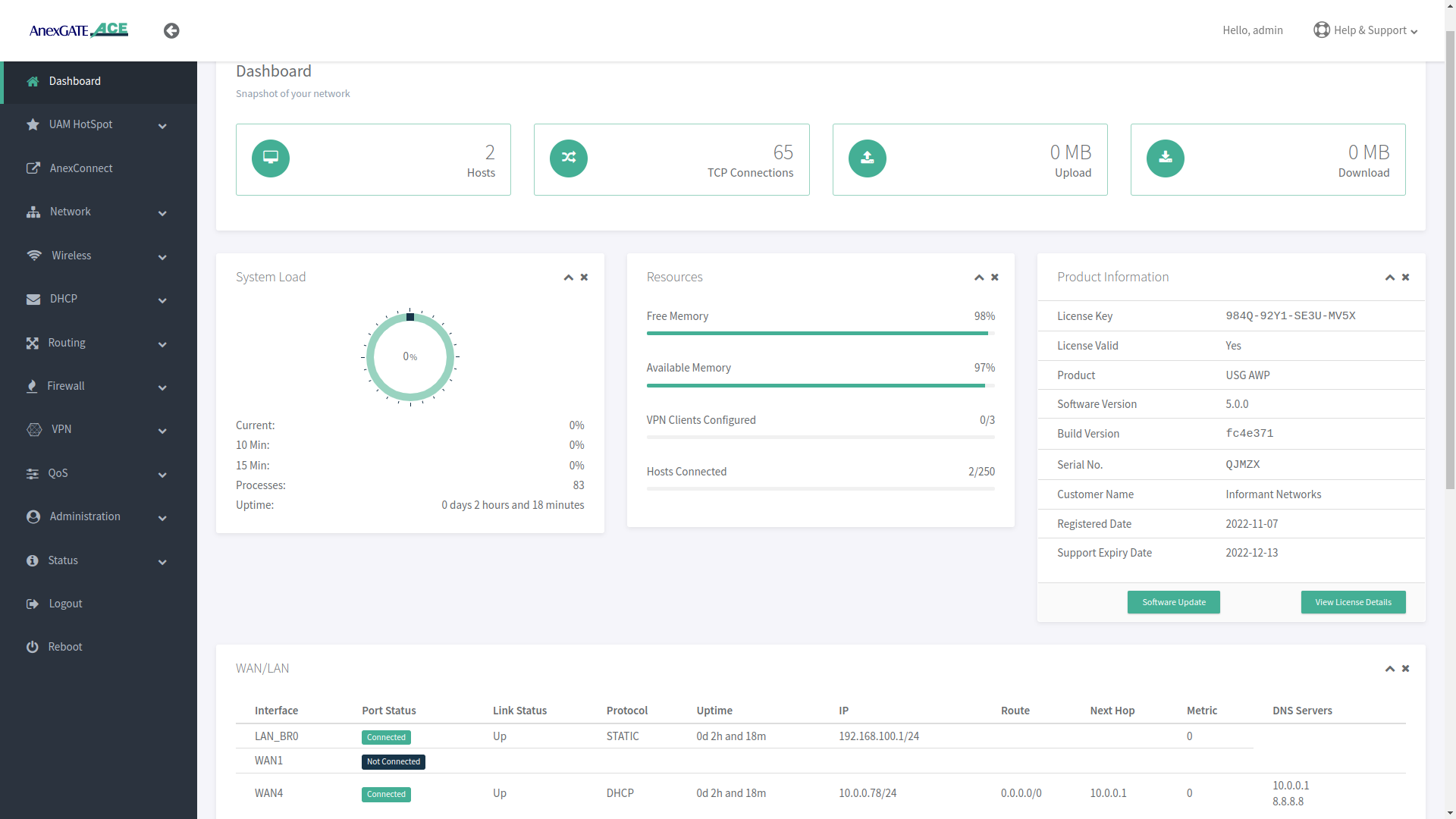
¶ AnexGATE ACE Dashboard
Dashboard allows the user to view the status of the device such as Hosts, TCP Connections, System Load, Download/Upload statistics, Connected LAN/WAN Interfaces, Product Info & status of the License and various other link statistics in one single pane.
The Product Information displays the License key and validity, Product model, Software Serial number, Customer Name, License registered date and Support Expiry.
Click on the View License Details tab for more information about the License and UAM Router.
NOTE:
- The License Key will be removed from the UAM Router if the software/hardware Reset has been performed or wrong license has been added in the UAM router.
- It is mandatory to have the valid License Key during the deployment of the UAM Router. If there is no License Key being shown. Contact the support to issue the License for that respective router. The License Key can be inserted by clicking on View License details which redirects to
Administration - Warranty and Licensepage if the Hardware or Software reset is performed on the UAM Router. - The LAN users will not have access to internet until and unless the license has been properly saved and validated under Warranty and License page once the
License keyhas been saved. - Before saving the License Key. Check if the router is able to access internet by going to
Status - System Commandandping google.com. Once the domain is pingable, Save the License Key. - License keys are unique to their respective UAM Routers. Make sure the proper License key is inserted. Failing to do so, the status of License key will appear as
Not Validcausing the LAN users to not have access to the internet.
¶ Setting up LAN Interfaces
LAN can be configured on any port of the AnexGATE router. There are 2 ways to configure LAN:
LAN Bridge- To configure LAN Bridge, go toNetwork - LAN Bridge.LAN Port- To configure LAN port, go toNetwork - LAN/WAN.
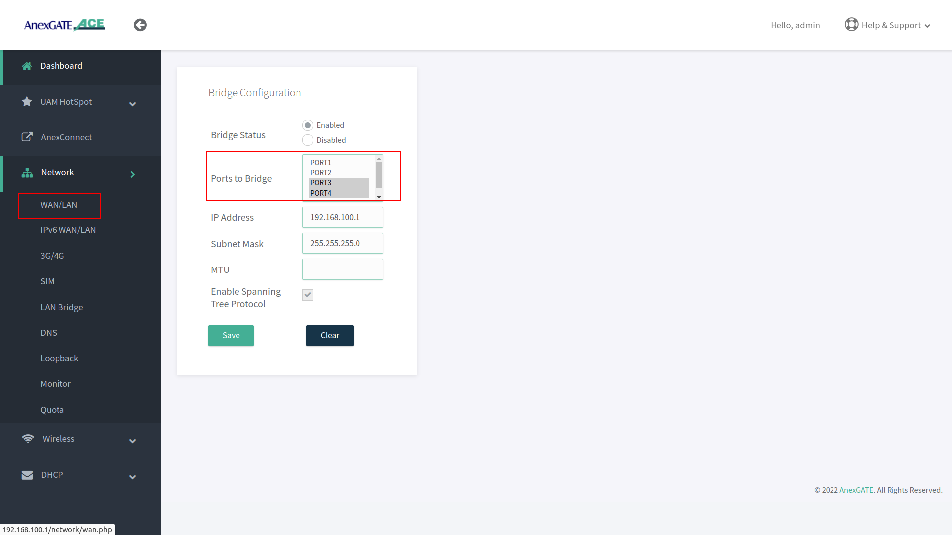
¶ Configure LAN Bridge
Multiple LAN interface ports can be grouped and configured as LAN Bridge which connect to same LAN gateway.
- To configure an individual port as
LAN Bridge. Go toNetwork - LAN Bridge. - Select Port number, Interface type and mode. Assign IP address and subnet mask on the ports which are to be configured as LAN Bridge.
NOTE:
- It is recommended to configure LAN under LAN/WAN if LAN interface is being configured on a single port for better network throughput.
- Avoid LAN network loop by enabling
Spanning Tree protocolif multiple ports are being configured under LAN bridge. - Carefully remove the ports from LAN bridge by clicking on disable if it is not being used. Read the warning instruction below.
Warning:
Before disabling or deleting any default interfaces. Make sure the LAN has been configured on other port and is in working condition by testing connectivity towards router and PC-machine.
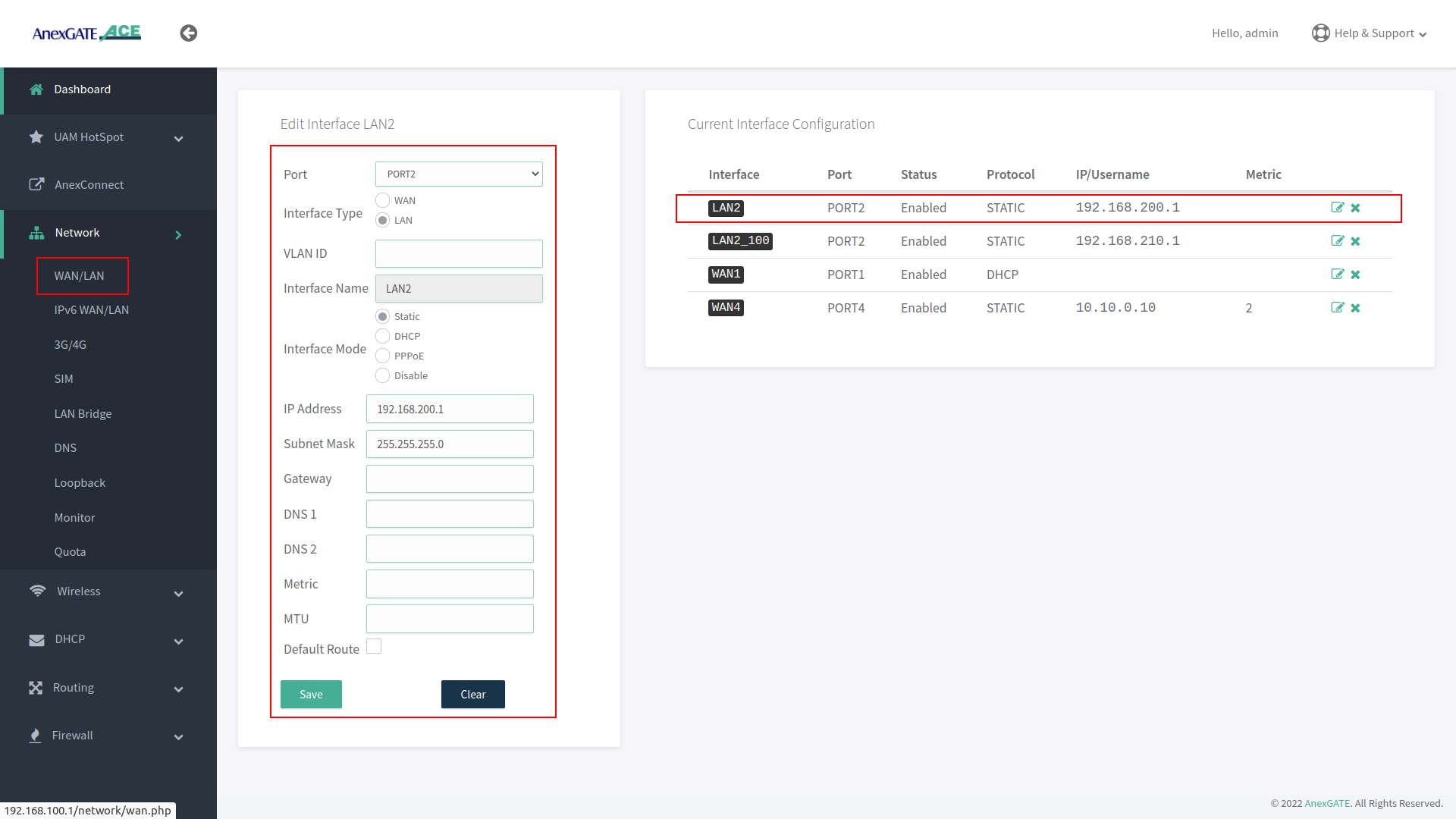
¶ Configure LAN Port
- To configure an individual port as
LAN Port. Go toNetwork - LAN/WAN. - Select Port number, Interface type and mode and assign IP address on a port which is to be configured as LAN.
The AnexGATE ACE Hotspot router has capability of configuring multiple LAN interfaces and Wifi Hotspot Instances.
NOTE:
- LAN Interface must be configured using Interface mode as “Static” and no metric must be mentioned. The LAN interface configured acts itself as a gateway.
- If two different LAN network segment are being configured, one as a regular LAN and another as a UAM Hotspot LAN. It is recommended to create separate zones instead of using same LAN zone for both LAN interfaces, to avoid unnecessary forwarding or conflicts in the network.
- LAN configured on the router physical port interface for Hotspot and configuring Hotspot network are two separate network entities. Hence, do not use overlapping network subnets while configuring the router interfaces.
IMPORTANT:
Configure LAN under LAN/WAN if only one port is being used on the AnexGATE ACE UAM Router to get maximum network throughput.
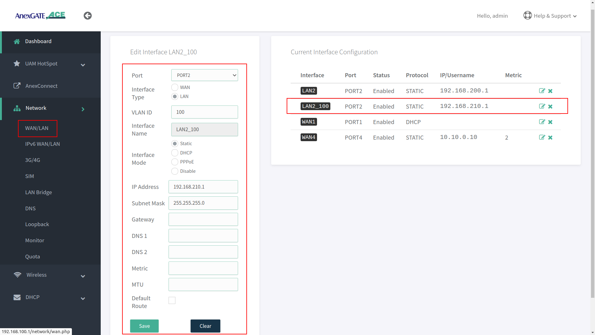
¶ Configure VLAN
- To configure an individual port as
VLAN. Go toNetwork - LAN/WAN. - Select Port number, Interface type,
VLAN IDinterface mode and assign IP address on a port which is to be configured as VLAN. - As shown in the image,
LAN2_100represents VLAN ID Tag 100 has been configured on LAN2 Interface.
NOTE:
- It is recommended to configure LAN interface before configuring VLAN interface in order to have router access via regular LAN port when network cable is connected directly to the router.
- Do not assign metric or enable default route for VLAN interfaces which are being configured as LAN.
- To remove the interface configuration, click on ‘X’ icon at the end of the configuration details. (Same condition applies for all to remove configuration done on the ACE UAM Router).
VLAN can be set on WAN Interface as well. Make sure that the upstream/opposite interface link is also configured as VLAN (tagged/trunk port).
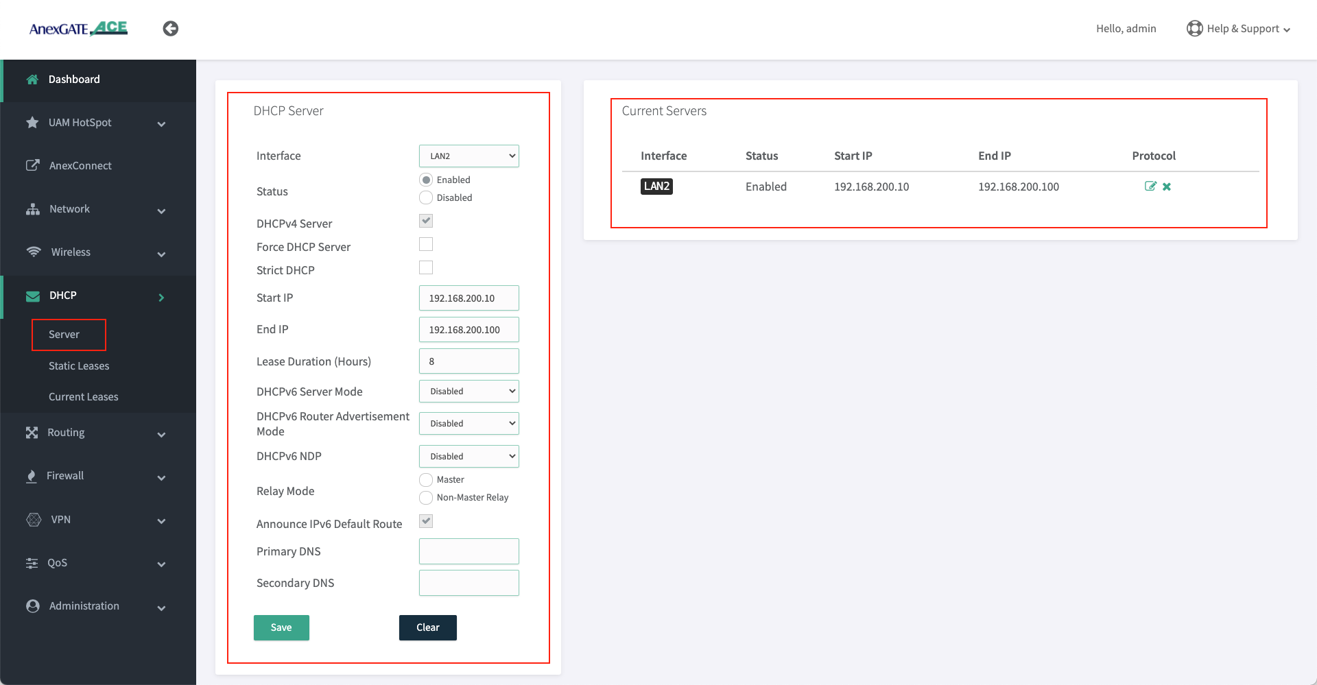
¶ Setting up DHCP Server for LAN (For Non-Hotspot Network Users)
- AnexGATE router can have multiple LAN interfaces. The router can be configured with normal DHCP server where the Non-Hotspot user can issue an IP Address via LAN DHCP Server and access internet without any authentication or authorization.
To configure DHCP Server for Non-Hotspot LAN, Go toDHCP - Server. - Following are the parameters required to configure a DHCP server for Non-Hotspot LAN port.
|
Elements |
Description |
|---|---|
Interface |
Select appropriate LAN/VLAN interface. |
Status |
Enable / Disable the VLAN DHCP Server. |
DHCP v4 Server |
Select this to enable DHCP v4 Server to assign IPV4 addresses to endpoints. |
Force DHCP Server |
Forces DHCP to serve IPs on the specified LAN interface even if another DHCP server is present on the same LAN network. |
Strict DHCP |
Select this to only assign IP addresses to endpoints which are added in DHCP - Static Lease. |
Start IP |
Assign beginning IP address from the DHCP pool for the specified network. |
End IP |
Assign ending IP address from the DHCP pool for the specified network. |
Lease Duration (Hours) |
Assign DHCP lease time for the endpoint connected to the specified network. |
Primary/Secondary DNS |
Assign Primary/Secondary DNS servers (optional). |
NOTE:
- LAN DHCP Server and UAM Hotspot DHCP server are two separate network entities. Normal LAN DHCP Server assigns IPs automatically for users to access internet without any authentication.
- UAM Hotspot Network or any other LAN/WAN network subnets must not overlap with each other. Make sure to assign different network subnets for any LAN/WAN network.
DO NOT use the same LAN interface to configure DHCP server on which the UAM Hotspot network has been configured. Either create a VLAN interface or use another port interface on the router to configure another LAN interface with DHCP Server.
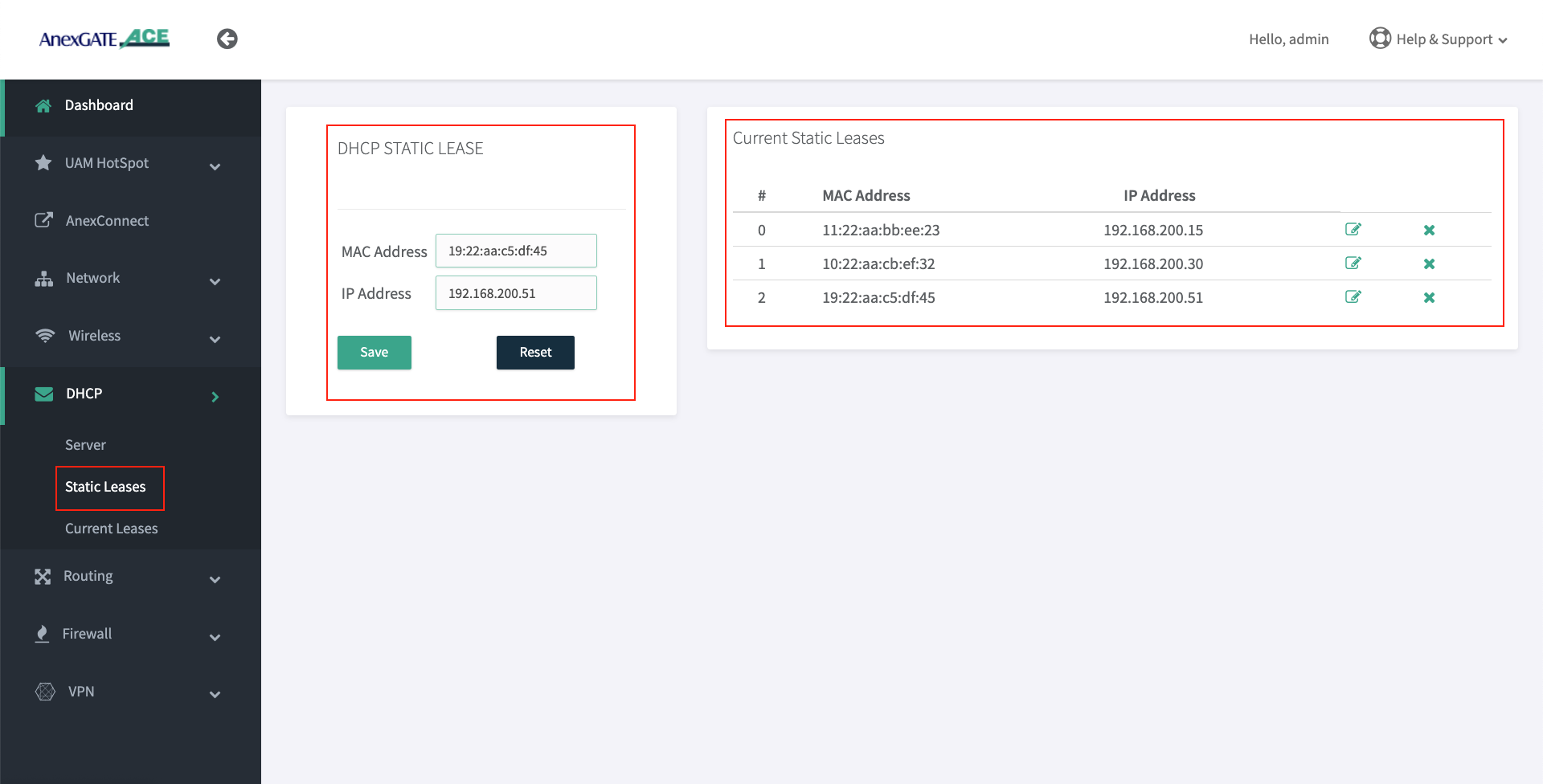
¶ Configure DHCP Static Lease (For Non-Hotspot Network users only)
DHCP Static Lease enables the device to bind MAC Address to the assigned IP Address. The IP address is reserved for the MAC Address.
- To configure DHCP Static Lease for Non-Hotspot LAN network, Go to
DHCP - Static Lease. - Assign IP address to the MAC Address as shown in the image.
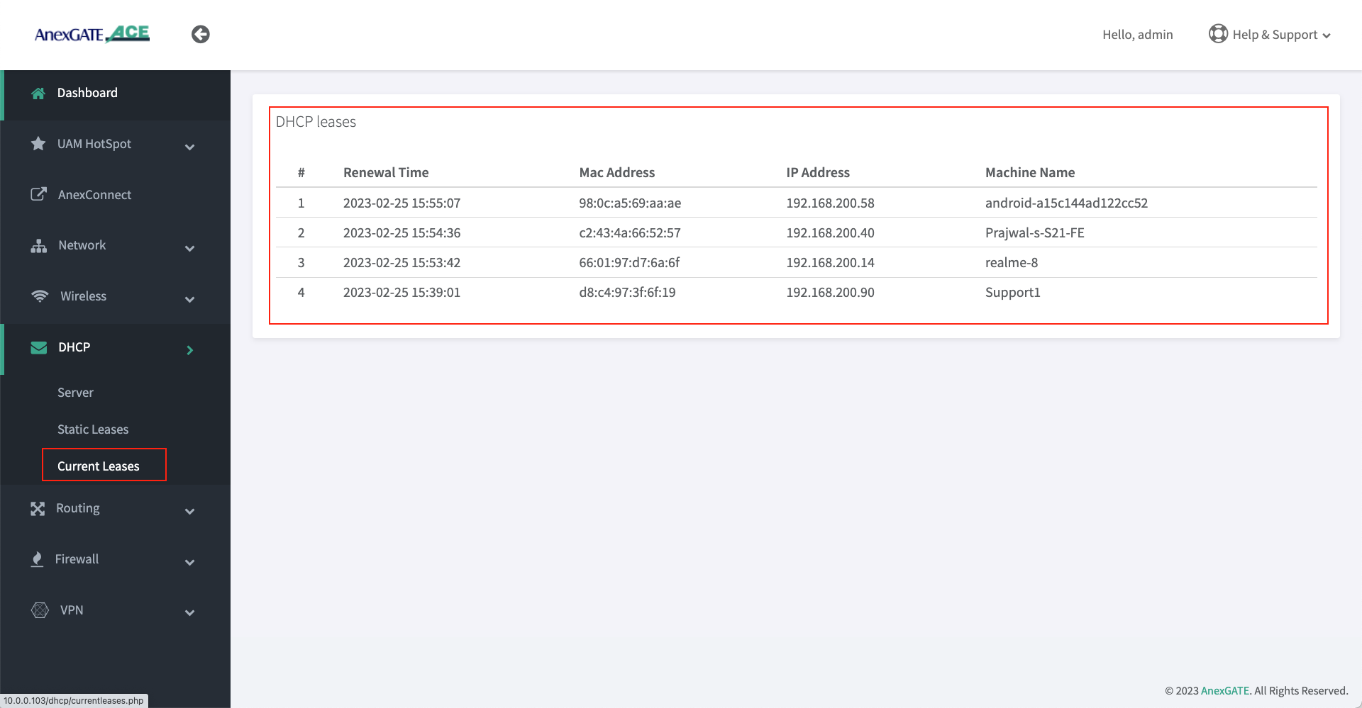
¶ DHCP Current Leases ( Non-Hotspot Network )
- DHCP Current Leases displays information such as IP Address, MAC Address and Hostnames of the endpoints which have been assigned IPs automatically via LAN DHCP Server (Non-Hotspot Network) as shown in the image below.
- To see the DHCP current leases, Go to
DHCP - Current Leases.
¶ Setting up WAN Interfaces
- AnexGATE router WAN interface can be configured in three ways. To configure WAN interface, Go to
Network - WAN/LAN
1. DHCP (Automatic IP assigned by the ISP Router)
2. Assigning Static IP Address with Gateway and DNS
3. PPPoE Dial Up on the AnexGATE ACE router.
NOTE:
- If there is a
Single WAN link, do not assign any metric on a WAN link interface under Metric Field while configuring. - If there are
Multiple WAN links, metrics(1,2,3) must be assigned to each WAN link interface to avoid network route problem and configure Load Balancing.
WAN can also be configured as VLAN by selecting WAN as interface type and assigning VLAN ID. Make sure the configured LAN/WAN interfaces are added under Firewall Rules in order to get the login page.
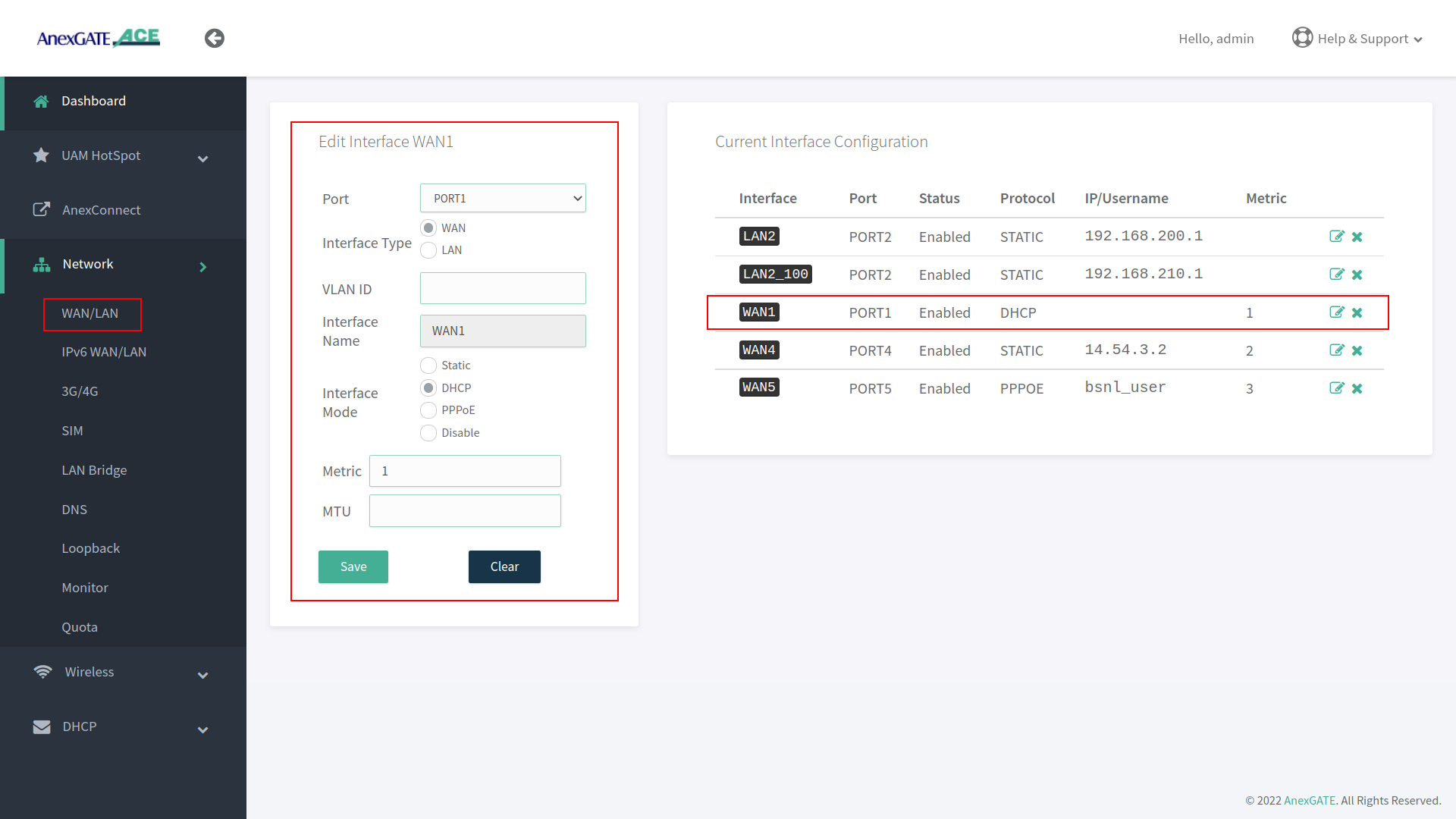
¶ Configure WAN via DHCP
To configure WAN to receive IP via DHCP server from the upstream router, Go to Network - WAN/LAN.
- Select Port, Interface Type and select Interface Mode as DHCP.
- Assign metric to the interface if multiple wan links are being configured.
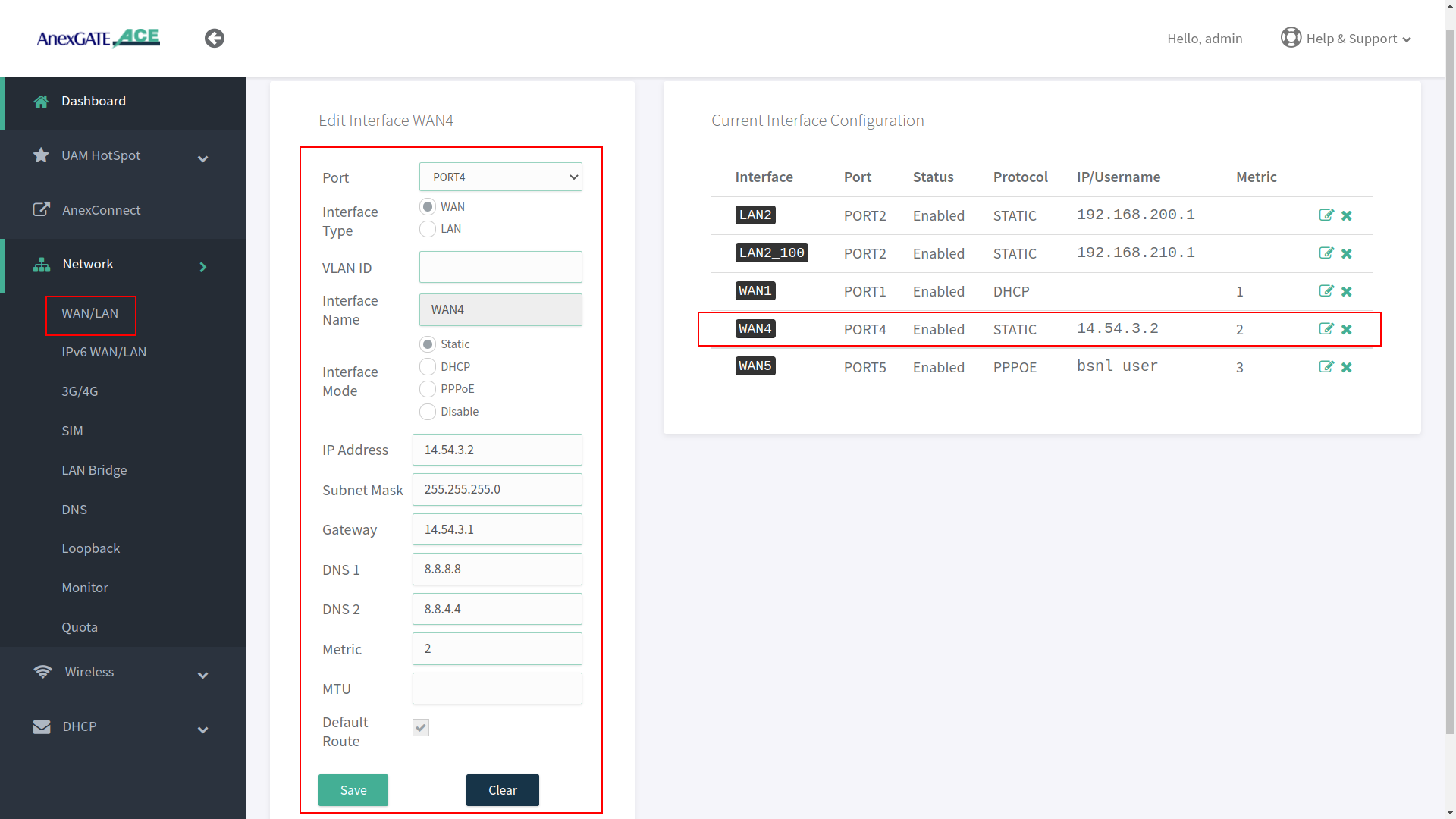
¶ Configure WAN as Static IP Address and DNS
To configure WAN as Static IP address, go to Network - WAN/LAN.
- Select Port, Interface Type and select Interface Mode as Static IP.
- Assign following parameters required for WAN configuration as shown in the image.
¶ Configure WAN as PPPoE Dial up
To configure WAN as PPPoE, go to Network - WAN/LAN.
- Select interface port, interface type as WAN, select Interface Mode as PPPoE.
- Assign PPPoE username and Password.
- Assign service name of the provider if necessary.
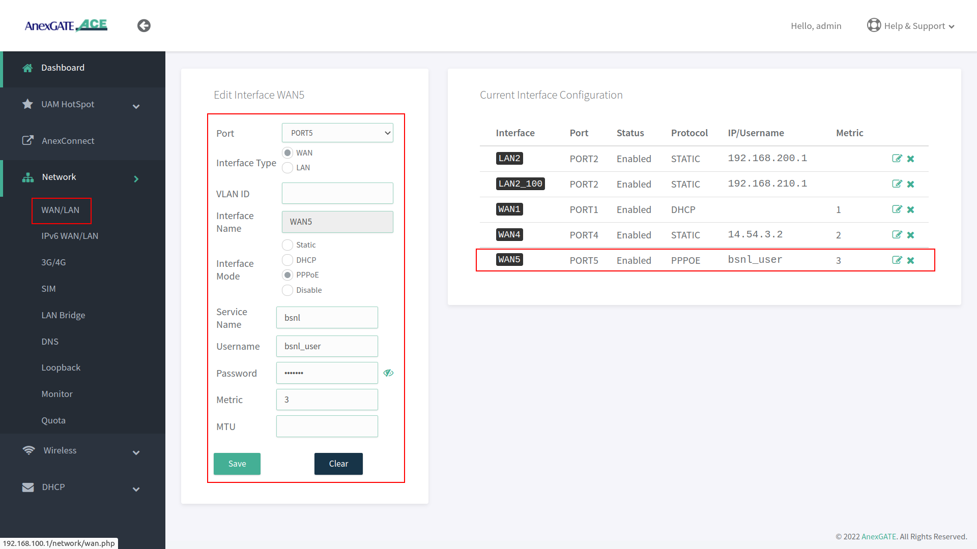
IMPORTANT NOTE:
Either remove 10.10.0.10 network configuration from the router at the end, after all necessary WAN / LAN and hotspot configuration is done or leave it as a backup port to access the router. If considering leaving it as a backup port access, assign metric 2 for it to not interfere with existing WAN network.
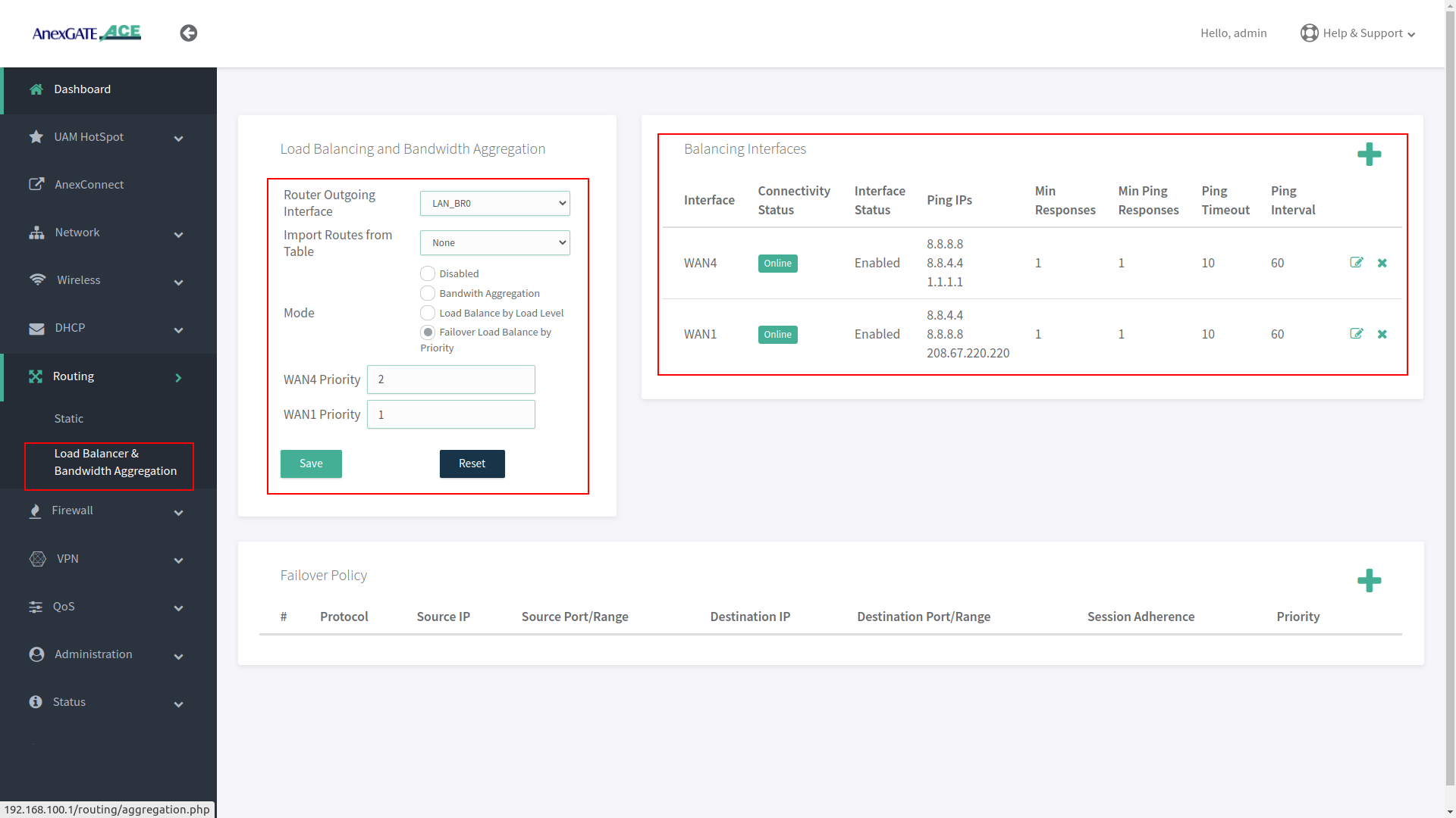
¶ Load Balancing and Bandwidth Aggregation
Load Balancing can be performed, if multiple links are being configured. The AnexGATE ACE Router supports 3 modes of Load Balancing.
- Bandwidth Aggregation
- Load Balance by Load Level
- Failover Load Balance by Priority
Balancing Interfaces has to be configured before setting up Load Balancing multiple links on the router.
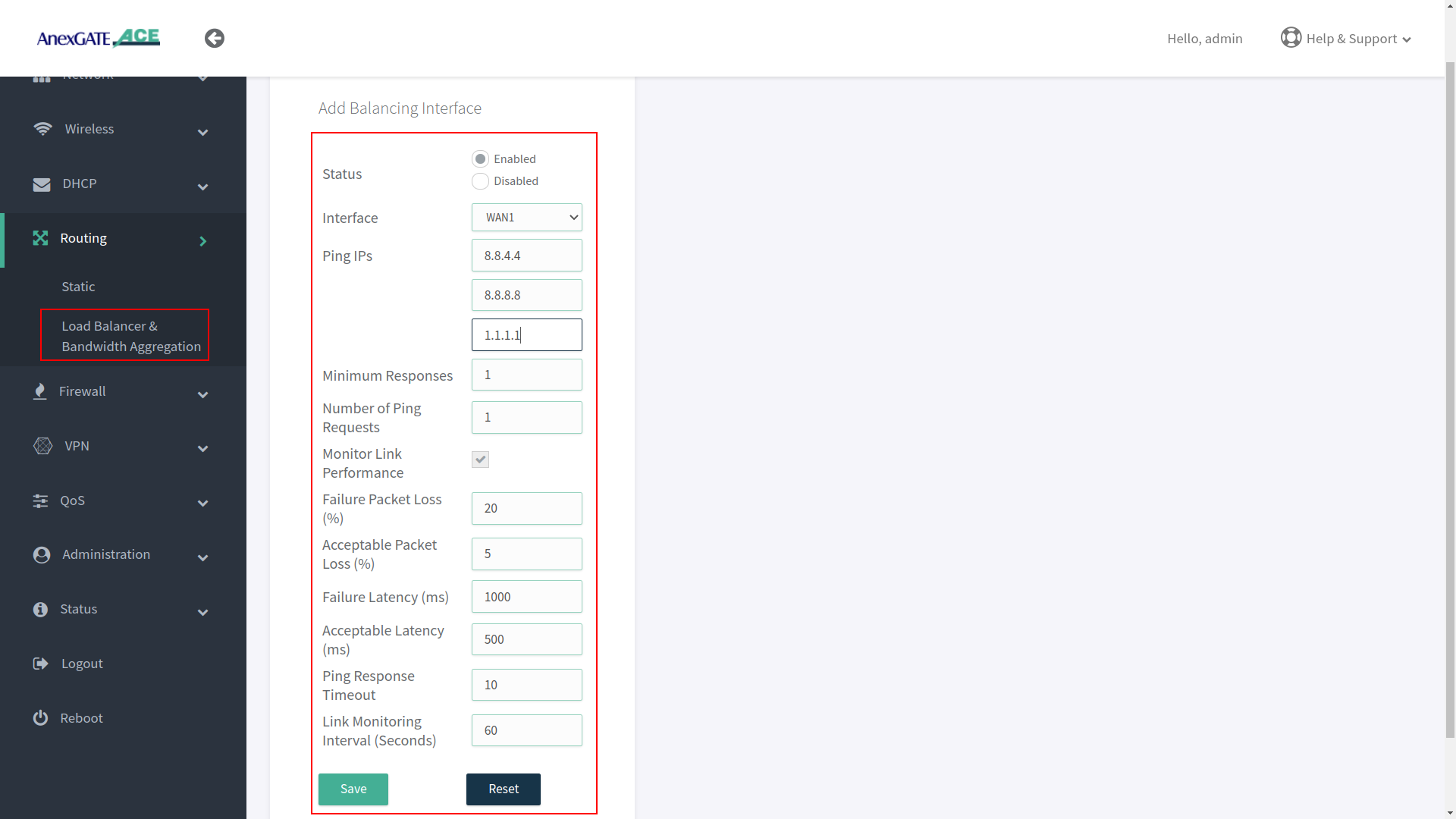
¶ Configuring Balancing Interfaces
WAN Interface/s must be added under Balancing interface in order to check the link status / reachability towards internet.
Following parameter values are added by default under Balancing interfaces.
| Element | Description |
|---|---|
Status |
Enable/Disable the configuration setting. Enable/Disable the configuration setting. |
Interface |
Select WAN interface to monitor Link Status. |
Ping IPs |
Assign Ping IPs to check if interface link status is still alive considering the reachability to them. |
Minimum Responses |
Number of Ping IPs that must reply for the link to be considered as successful. |
Number of Ping Requests |
Number of echo requests to send to each IP to check link status. |
Monitor Link Performance |
Enable this to check the overall link quality with packet loss and/or latency measurements. |
Failure Packet Loss (%) |
Maximum percentage of packet loss for a WAN link to be considered as DOWN when Monitor Link Performance is enabled. |
Acceptable Packet Loss (%) |
Minimum percentage of packet loss for a WAN link to be considered as UP when Monitor Link Performance is enabled. |
Failure Latency (ms) |
Maximum packet latency in milliseconds for a WAN link to be considered as DOWN when Monitor Link Performance is enabled. |
Acceptable Latency (ms) |
Minimum packet latency in milliseconds for a WAN link to be considered as UP when Monitor Link Performance is enabled. |
Ping Response Timeout |
Number of seconds to wait for ping response once a ping-request is sent from a WAN link before considering as lost. |
Link Monitoring Interval (seconds) |
Number of seconds between each Link Status check of WAN interfaces. |
NOTE:
- Initially, WAN interfaces are configured under Balancing and are in disabled state. Click on Add (+)/Edit and Enable the WAN link.
- While configuring Balancing interface
Performance Link Monitormust be enabled in order to receive the Latency report in AnexCONNECT portal. - Enable WAN Link under Balancing Interfaces even if there is single WAN link configured and Enable Monitor Link Performance in order to receive telemetry status & Latency Report in
AnexCONNECTportal.
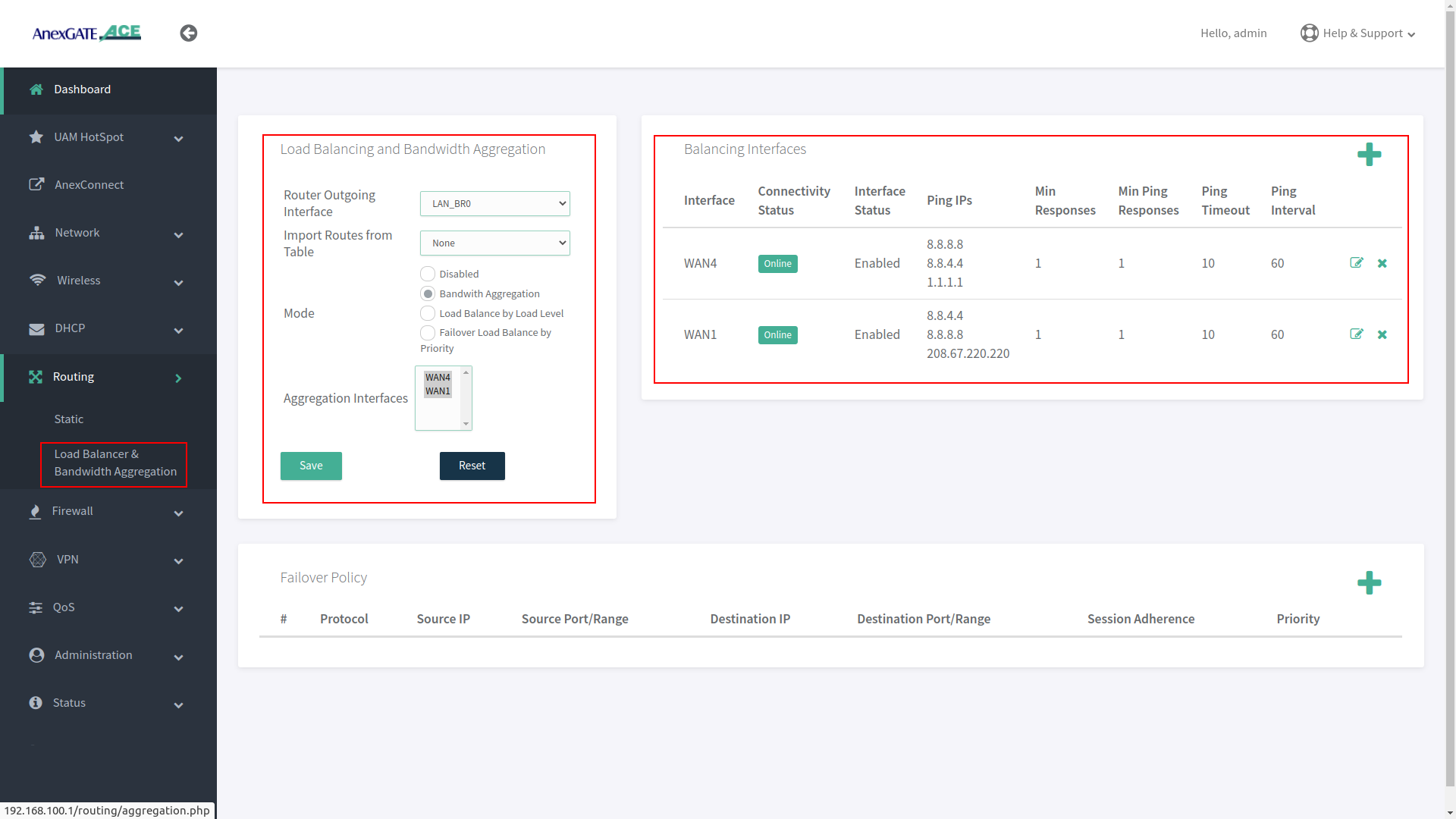
¶ Load Balancing
Load Balancing needs to be configured when there are multiple WAN links being added in the router for Internet Redundancy.
Following are the Load Balancing Techniques which can be configured in AnexGATE Router:
| Elements | Description |
|---|---|
Router Outgoing Interface |
Working LAN Interface needs to be selected. |
Import Routes from Table |
Import routes from specific IP rule list. Default = None. |
| Modes | |
Bandwidth Aggregation |
Multiple WAN Links configured are in Active-Active State where LAN systems can initiate TCP connection/session on any of the configured multiple WAN Link. |
Load Balance by Load Level |
Inbound/outbound Traffic flow can be configured on WAN links in terms of percentage equal to 100. Example: WAN1 = 70% - Most of the traffic will flow through link WAN 1. WAN2 = 30% - Less traffic is directed over WAN 2 link. |
Failover Load Balance by Priority |
WAN Traffic will be initially flowing on WAN link with “Priority 1” as primary.
|
¶ Bandwidth Aggregation
Under Bandwidth Aggregation, both the links are in Active - Active state where TCP sessions/connections are established on one or other WAN port randomly.
If one link goes down the other links will act as a backup. If any TCP connection has been established on a link and that link goes offline, reload the browser to establish TCP session/connection on other link or start another ping session if testing.
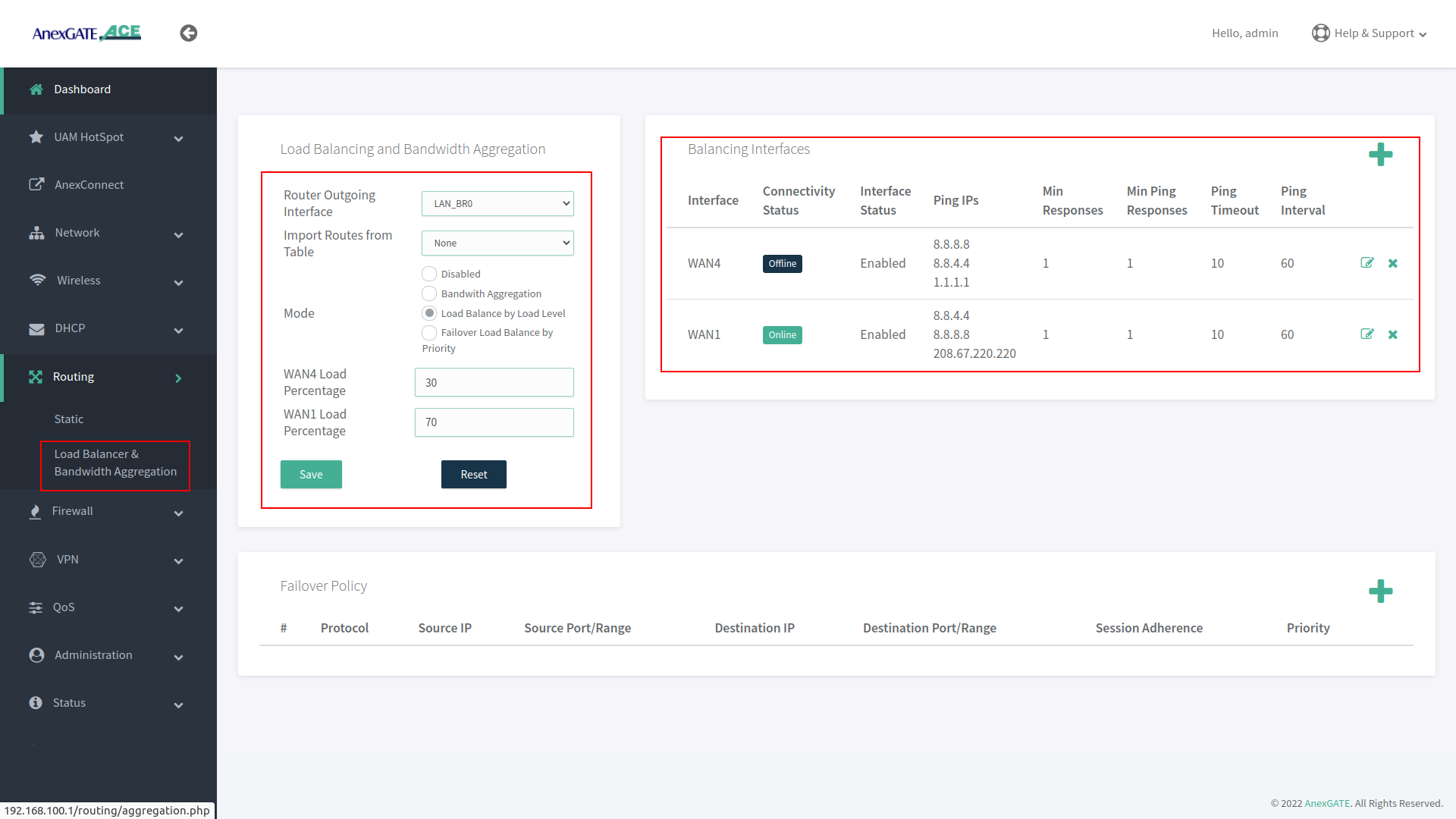
¶ Load Balance by Load Level
Under Load Balance by Load Level, Both the links can be configured as per basis of weight. As shown in the image, WAN 1 is configured to handle 70 percent of traffic load flow through the link and WAN 2 is configured to handle 30 percent of traffic load flow.
If one of multiple WAN links goes down or offline, whole traffic load will be shifted to secondary link.
¶ Failover Load Balance by Priority
Under Failover Load Balance by Priority, WAN links are in Active - Passive state where Low Priority metric (1) takes precedence and become primary over other configured WAN links.
Initially, all the traffic flow will be on Primary Link with low metric priority. If the Primary link fails to reach/ping IPs per basis conditions applied in Balancing Interfaces, it will failover to secondary link according to the priority metric assigned. This usually takes a minute to failover to secondary link. This can be adjusted under Balancing Interfaces as per parameters mentioned above.
If the Primary link comes online, the secondary link will get rolled back over to primary link without any interruption in the local network.
¶ Setting up the Firewall
The firewall configuration is fairly straight forward and automatically provides the router with a base rule set of rules and an understandable configuration file for additional rules.
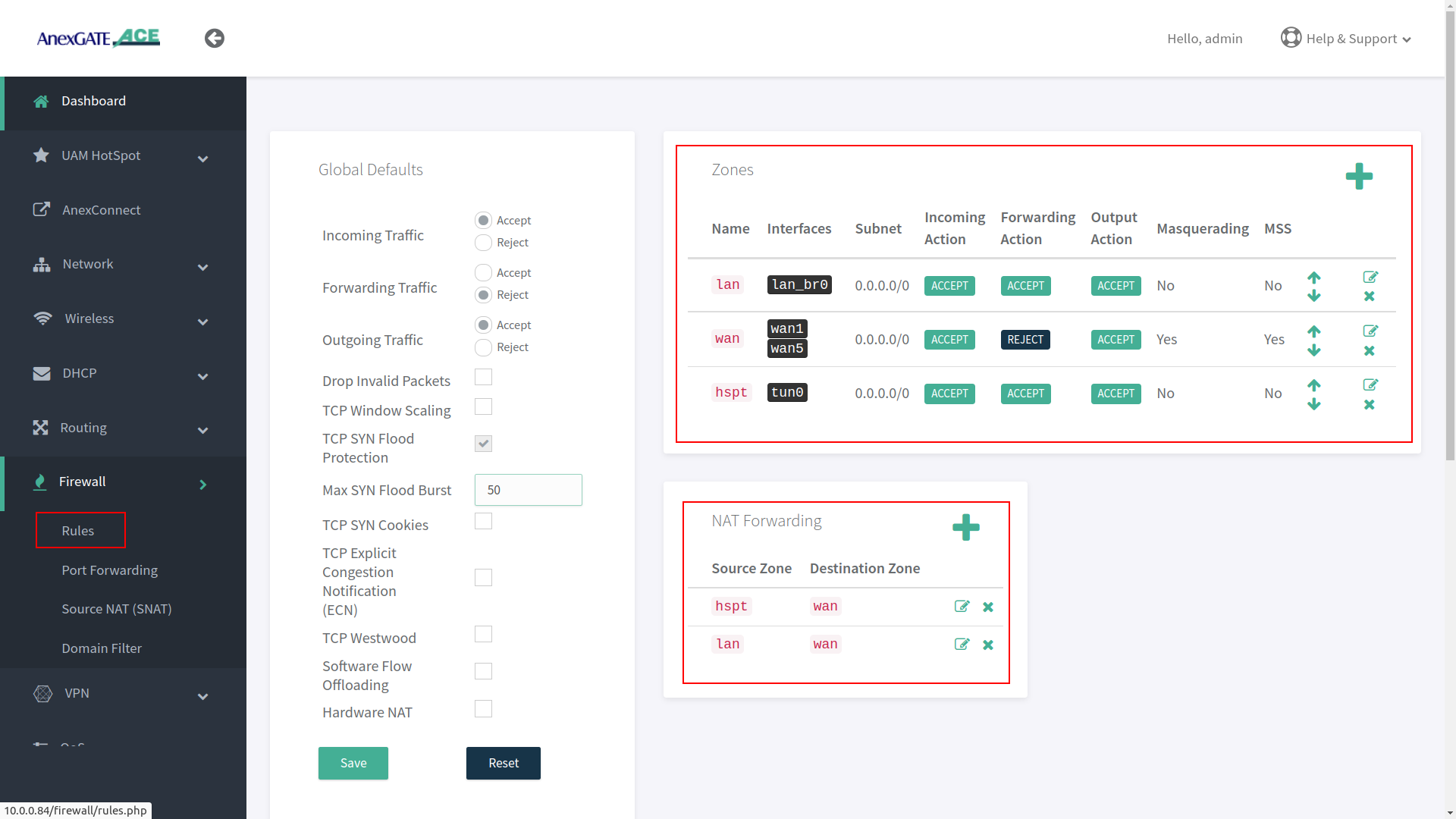
¶ Firewall Zone
To configure a Firewall Zone, Go to Firewall - Zones.
- A
firewall zonegroups one or more interfaces under a zone and serves as a source or destination for traffic forwarding. - To configure Multiple WAN/LAN Interfaces under Firewall Zones, select and edit “WAN” Zone, and add configured WAN Interfaces (WAN1 and WAN5 are added in the WAN Zone by default).
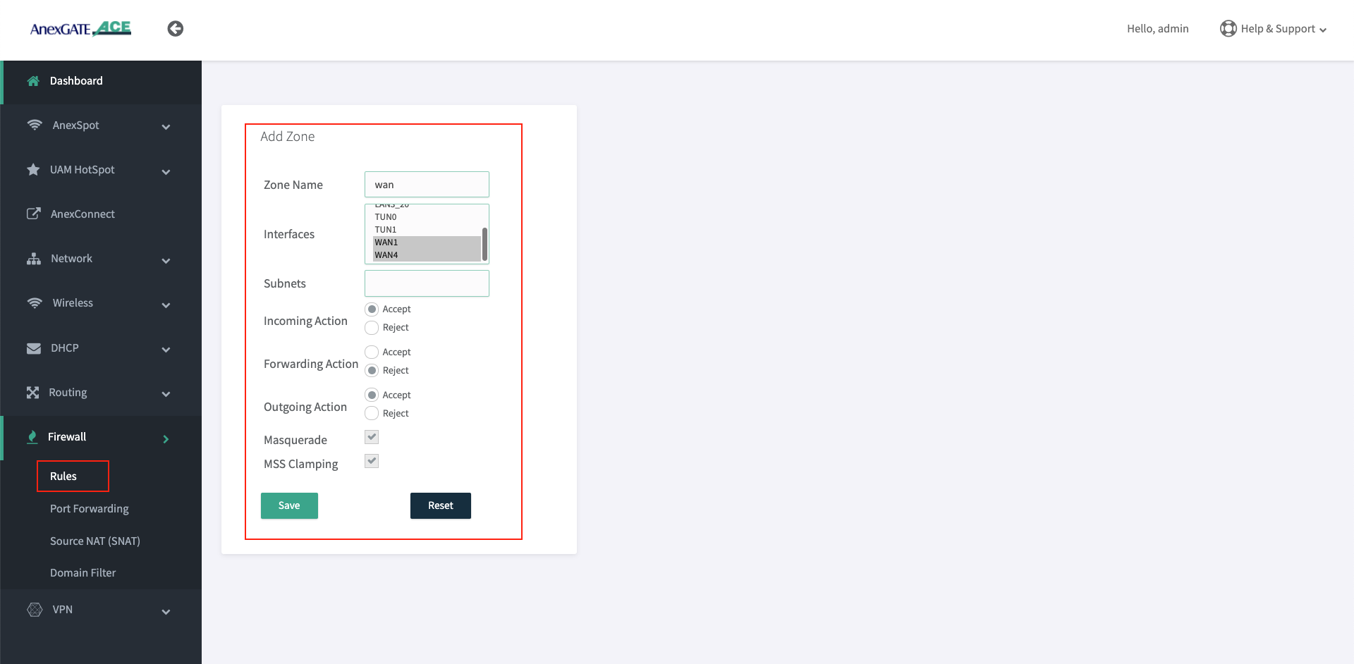
- ADD or EDIT
LANWANHSPTIPSECzone and select multiple interfaces to add by pressingCtrlbutton and click on the interface (WAN1, WAN2, WAN3, USB0) as per requirement as shown in the image below.
¶ Adding Interfaces in LAN Zone:
Select appropriate LAN interfaces from the list in order to add the interfaces under LAN Zone.
NOTE:
- Multiple interfaces added under same Zone will communicate each other since the Forwarding Action is under
ACCEPTstate. - It is recommended to create an another Firewall zone for that respective LAN/WAN interface to block such connectivity between different LAN Segments.

¶ Adding Interfaces in WAN Zone:
Select appropriate WAN interfaces from the list in order to add the interfaces under WAN Zone.
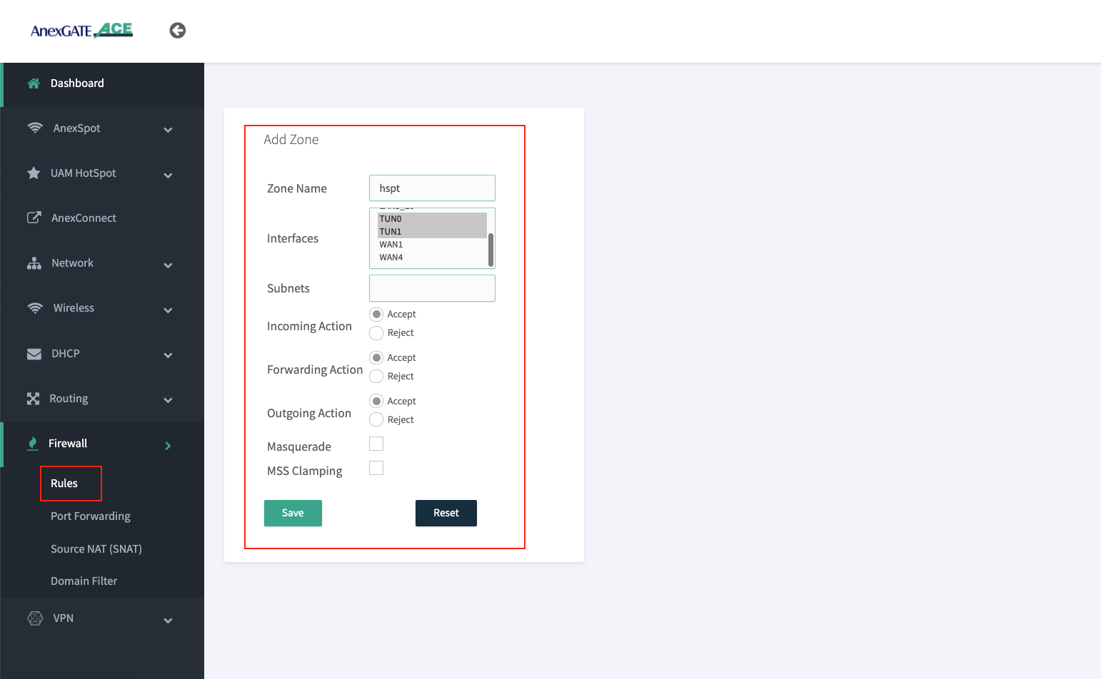
¶ Adding Interfaces in HSPT Zone:
Select appropriate Hotspot (tun) interfaces from the Inteface list in order to add the interfaces under HSPT Zone.
Below image shows TUN0 & TUN1 interfaces as there are two Hotspot Instances configured. By default, TUN0 is added under hspt zone.
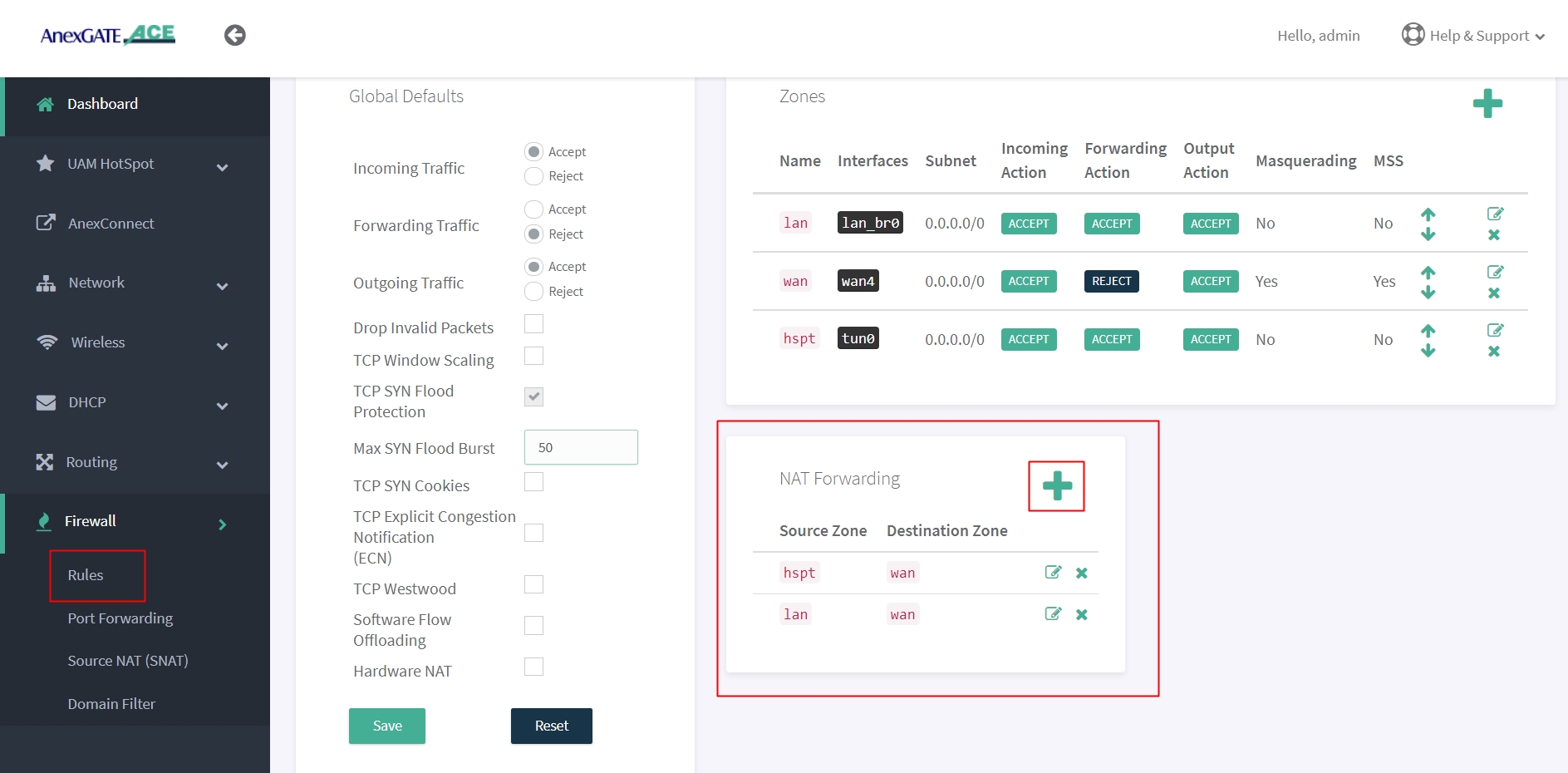
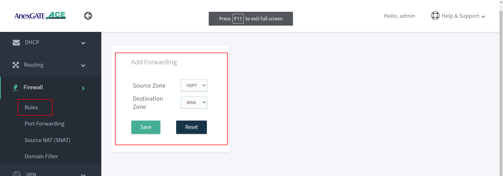
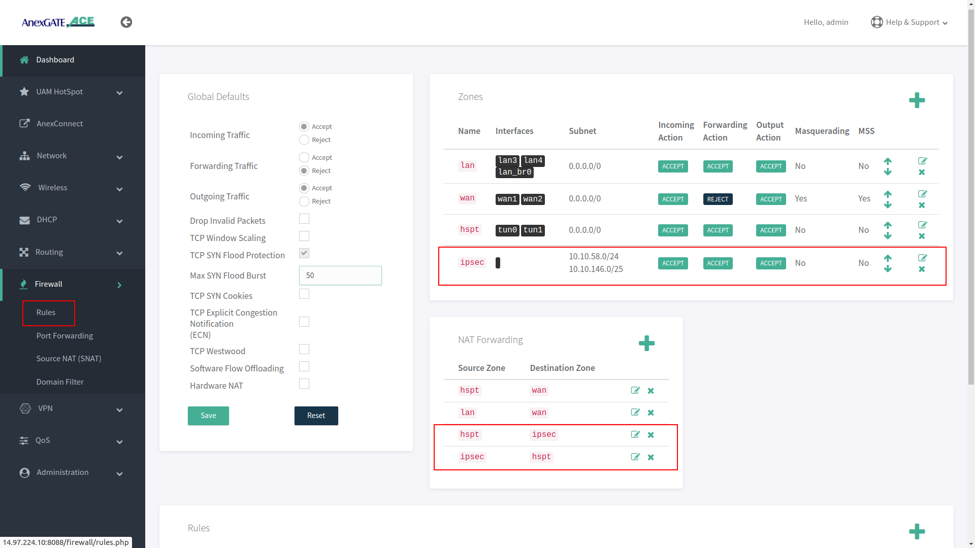
¶ NAT Forwarding
NAT Fowarding controls the traffic flow between zones. Under NAT Fowarding, click on + icon.
By default, the NAT Forwarding is done on following zones.
- Source Zone:
lanDestination Zone:wan - Source Zone:
hsptDestination Zone:wan
NOTE:
- After configuring LAN/VLAN or WAN interfaces, make sure to add the interfaces under their respective Firewall Zones. If not properly configured, the access login page will not appear when connected to LAN.
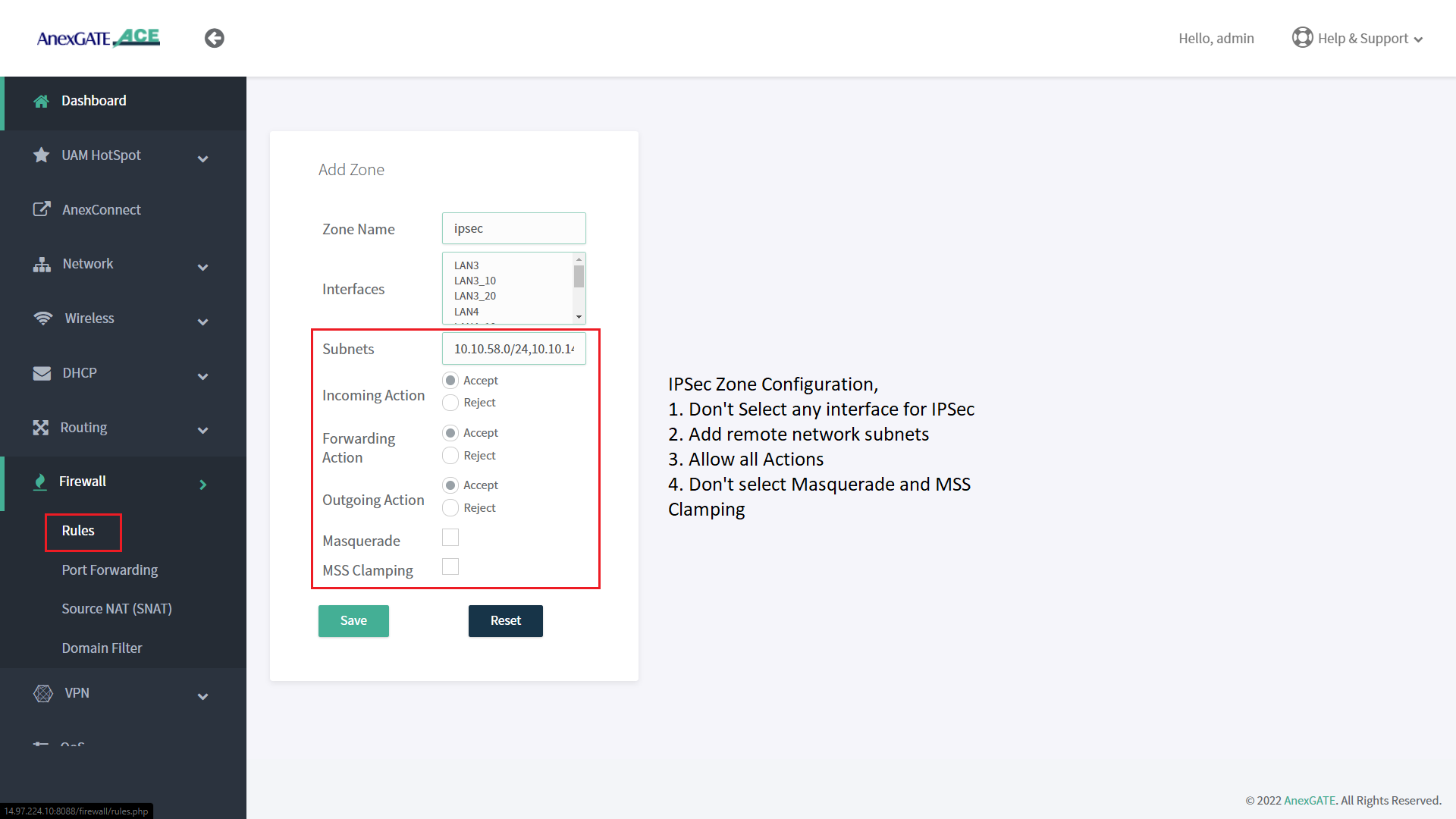
- Create IPSec Zone and add remote subnet without selecting any interfaces and all Firewall actions will be in ACCEPT condition.
- For IPSec, NAT Forwarding must be configured as follows:
Source Zone: lan Destination Zone: ipsec
Source Zone: ipsec Destination Zone: lan
- If the UAM Hotspot Router has two different LAN segments under two different zones, Example: Zone 1 - HSPT [Hotspot] and Zone 2 - LAN2 [Normal LAN] and the user wants both zones to communicate with each other.
Add Nat Forwarding Rule as follows:
Source Zone: lan2 Destination Zone: hspt
Source Zone: hspt Destination Zone: lan2
IMPORTANT NOTE :
Only AUTHENTICATED users under UAM HOTSPOT Network will be able to communicate with the other zone Network Segment that has been added under NAT FORWARDING
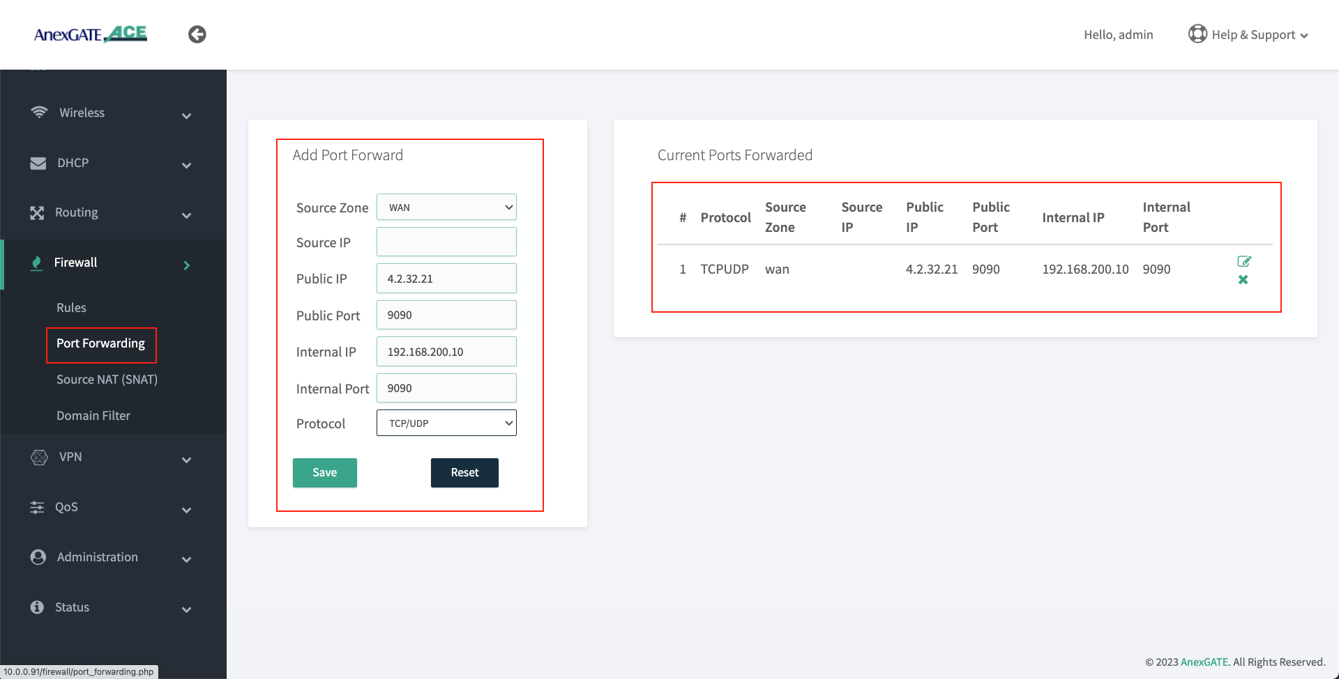
¶ Port Forwarding
Port Forwarding allows AnexGATE router to send any incoming data request from the internet on WAN to a specified device in LAN network.
To configure Port Forwarding rule, Go to Firewall - Port Forwarding.
| Elements | Description |
|---|---|
Source Zone |
Select the WAN Zone as a Source to listen to the incoming connections. |
Source IP |
Assign Source IP to only get port forward only for specific request from source IP address. Leave blank to allow all wan requests. |
Public IP |
Enter Public WAN IP configured/terminated on the Router WAN port to port forward requests to internal (LAN) IP. |
Public Port |
Enter Public Port to accept WAN requests to be port forwarded only for that specific port. |
Internal IP |
Enter LAN IP Address for WAN requests to be redirected towards internal (LAN) IP. |
Internal Port |
Enter Internal Port that is listening to requests on the mentioned internal (LAN) IP. |
Protocol |
Specify TCP, UDP or both TCP/UDP protocols. |
NOTE:
Following conditions must be followed in order for Port Forwarding to work properly.
- Assign Manual Static LAN (Internal) IP Address/Gateway/DNS information from the UAM Hotspot network subnet on the user's PC-Server that needs to be Port Forwarded.
- Bypass MAC Address of Users's PC-Server under UAM Hotspot Configuration by going to
UAM - Configure. - Add Port Forwarding rules as shown in the above image.
TROUBLESHOOTING PORT FORWARDING:
- Verify whether the service port is under
LISTENINGstate in the user's PC-Server usingnetstatcommand.
For Windows - netstat -qn
For Linux - netstat -tuln
- Make sure the server is accessible from the UAM Hotspot / LAN Network.
- After configuring Port Forwarding under UAM Hotspot Router, verify if the port is in
OPEN or CLOSEDstate by visiting ping.eu website to check the port. - Use
NMAP/ZENMAPpackage to check the port state inLinux/Windows. - If the port state shows as
FILTEREDwhich means that it is blocking the inbound requests towards LAN IP/Port Address that has been port forwarded to.
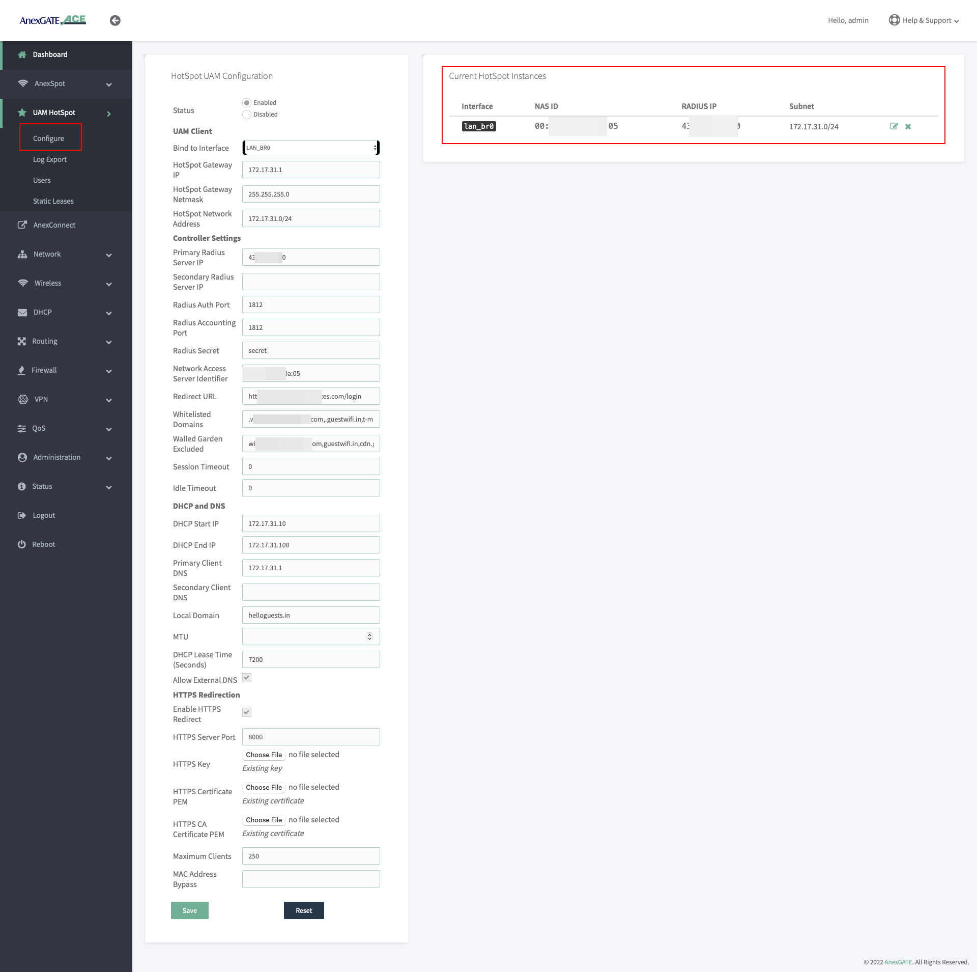
¶ UAM HotSpot Configuration
UAM Hotspot is an Internet access controller that provides a captive portal / walled-garden environment and uses RADIUS or a HTTP protocol for access provisioning and accounting.
To configure ACE HOTSPOT service,
Go to UAM Hotspot - Configure.
¶ Managing UAM HotSpot
| Name | Description |
|---|---|
Status |
Enable/Disable Hotspot Configuration. |
| UAM Client | |
Bind to Interface |
Select the LAN interface to be configured as UAM Hotspot. Example: |
Hotspot Gateway IP |
Assign UAM Hotspot Gateway IP. Example: 172.17.31.1 |
Hotspot Gateway Netmask |
Assign UAM Hotspot Subnet Mask. Example: 255.255.255.0 |
Hotspot Network Address |
Assign UAM Hotspot Network Address. Example: 172.17.31.0/24 NOTE: UAM Hotspot Network Address supports maximum of 255.255.0.0 or /16 subnet mask. |
| Controller Settings | |
Primary Radius Server IP |
Enter Primary RADIUS Server IP. |
Secondary Radius Server IP |
Enter Secondary RADIUS Server IP if necessary. |
Radius Auth Port |
Enter RADIUS Authentication Port. |
Radius Accounting Port |
Enter Radius Accounting Port. |
Radius Secret |
Enter RADIUS passphrase. |
Redirect URL |
Enter Redirect URL as necessary. |
Network Access Server Identifier |
Network Access Server identifier should be added in such format given as aa:bb:cc:11:22:33. Add MAC Address mentioned in NOTE: If the device is previously configured with mac address as Network Access Server (NAS) ID under UAM Hotspot and the mac address gets changed after firmware upgradation. The old NAS ID mac address is still valid and can be used to configure UAM Hotspot on the updated router. |
Whitelisted Domains |
Add required Domains to be whitelisted from being Authenticated. Example: .cdn.wifihotspot.io,.cdnhotspot.azureedge.net |
Walled Garden Excluded |
Add required Domains and IPs to be whitelisted from Authentication. Example: cdn.wifihotspot.io,cdnhotspot.azureedge.net,4.24.3.10 |
Session Timeout |
Set Session Timeout for the user to be de-authenticated from RADIUS Server in seconds. 0 = unlimited. |
Idle Timeout |
Set Idle Timeout for the user to be de-authenticated from the Hotspot Router in seconds. 0 = unlimited. |
| DHCP and DNS | |
DHCP Start IP |
Set DHCP Start IP from the UAM Hotspot Example: 172.17.31.2 Note: Do not assign Start IP as 172.17.31.1 since that IP has been configured as the gateway. |
DHCP End IP |
Set DHCP End IP for the UAM Hotspot. Example: 172.17.31.100 Note: DHCP Range must be within the Subnet Mask of the Hotspot Network Address. |
Primary Client DNS |
Set Primary Client DNS for the UAM Hotspot. Example: 172.17.31.1 NOTE: Primary Client DNS must be set as the UAM Hotspot Gateway. |
Secondary Client DNS |
Set Secondary Private Client DNS for UAM Hotspot if necessary. NOTE: Do not assign Public DNS IP under Primary or Secondary Client DNS. |
Local Domain |
Enter Local Domain for the Hotspot Router. |
MTU |
Set MTU if necessary (Optional). |
DHCP Lease Time (Seconds) |
Set DHCP Lease time for Hotspot network in seconds. |
Allow External DNS |
Enable Allow External DNS. |
| HTTPS Redirection | |
Enable HTTPS Redirect |
Enable this for HTTPs Redirection. |
HTTPS Server Port |
Enter HTTPs Server Port. |
HTTPS Key |
Upload HTTPS Key. |
HTTPS Certificate PEM |
Upload HTTPS Certificate PEM. |
HTTPS CA Certificate PEM |
Upload HTTPS CA Certificate PEM. |
Maximum Clients |
Enter Number of Maximum Clients to assign IP address. NOTE: This is total number of users both Authenticated and Non-Authenticated. |
MAC Address Bypass |
Enter MAC Address of the machines to be bypassed from Authentication. Example: aa:bb:cc:dd:11:22 NOTE:
|
SAVE |
Save the settings of the UAM Hotspot. |
¶ Verify UAM HotSpot Interface
After configuring the UAM Hotspot and saving the settings. To verify if the UAM Hotspot Instance has been created.
- Go to
Status - System Command. - Run
ifconfigcommand to see if the interface tun0 has been added into the network.
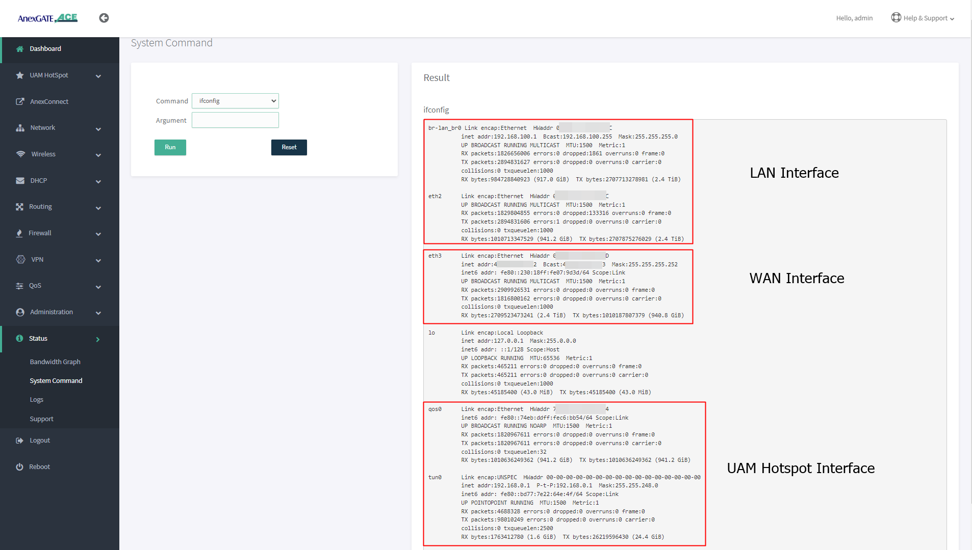
NOTE:
- Configuring multiple hotspot instances will have multiple interfaces created for UAM Hotspot such as
tun0tun1if seen underifconfigstatus command. - By default, only 1 UAM Hotspot Interface is added into
hsptzone astun0underFirewallzones. - If second instance of UAM Hotspot has been configured then
tun1interface will created for the second UAM Hotspot instance. tun1interface must be added by creating different zone (examplehspt2) underFirewall - Rulesfor the UAM Hotspot instances to function properly.- It is recommended to configure different zones under
Firewall - Rulesand add NAT Forwarding accordingly for reachability towards different network segments to avoid any kind of Router services or network conflicts.
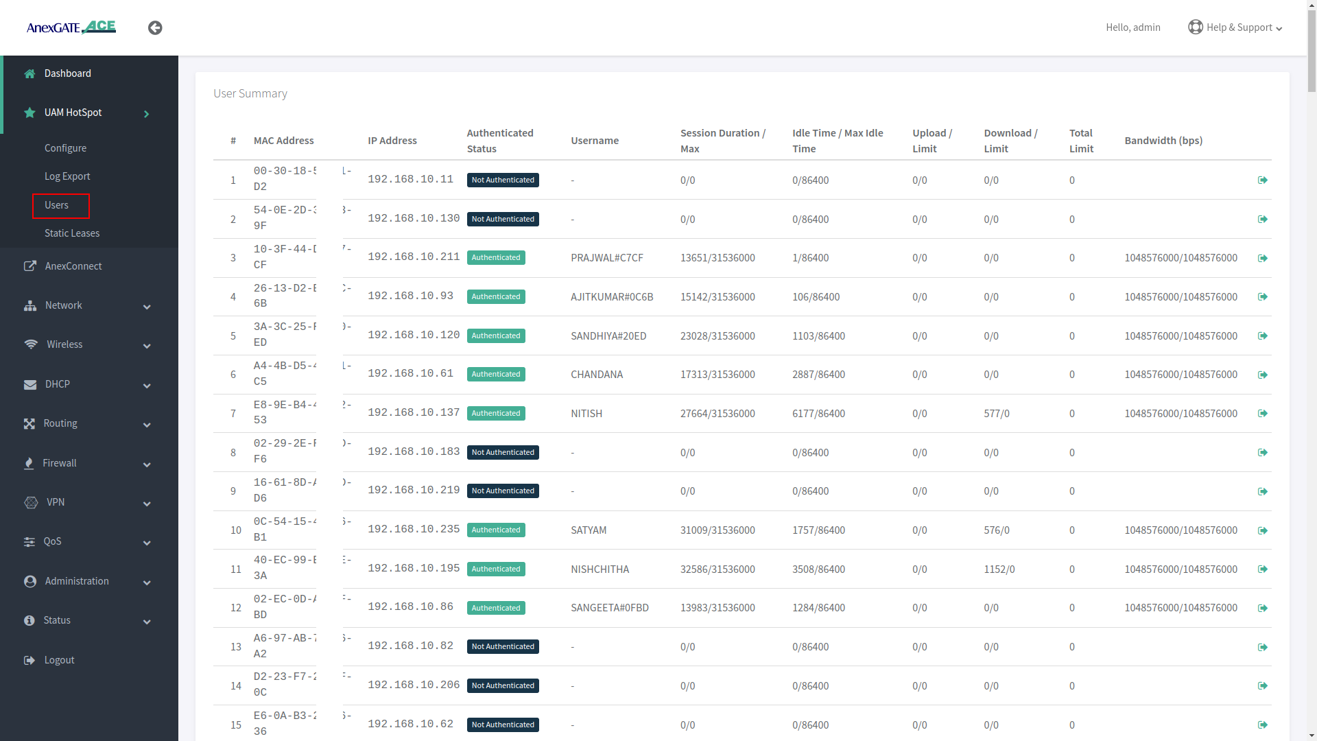
¶ Users in UAM HotSpot
The devices which connect to the ACE router will be assigned an IP Address through HotSpot DHCP Server. These endpoint devices are then summarized under Users of UAM Hotspot.
To view the UAM Hotspot users, Go to UAM Hotspot - Users.
The User Summary will be shown as follows once a device gets connected to the UAM HotSpot for Network Access.
| Name | Description |
|---|---|
MAC Address |
Displays MAC Address of the endpoint device who has been assigned an IP Address by Hotspot DHCP Server. |
IP Address |
Displays IP Address assigned by Hotspot DHCP Server automatically. |
Authenticated Status |
Displays endpoint device status in terms of Authenticated or Not Authenticated by the Radius Server. |
Username |
Displays the Authenticated user username. |
Session Duration |
Displays Session Duration of the Authenticated user from the Radius Server side. |
Idle Timeout |
Displays the Idle Timeout duration where the user will get logged out once the time duration surpasses the actual timeout value. |
Upload Limit |
Displays the Upload Statistics (in bytes) of the Authenticated user. |
Download Limit |
Displays the Download Statistics (in bytes) of the Authenticated user. |
Total Limit |
Displays the Total limit of Upload / Download (in bytes) the user can avail before he gets logged out once the limit is surpassed. |
Bandwidth |
Displays the Bandwidth allotted by RADIUS Server to the Authenticated user (in bps). |
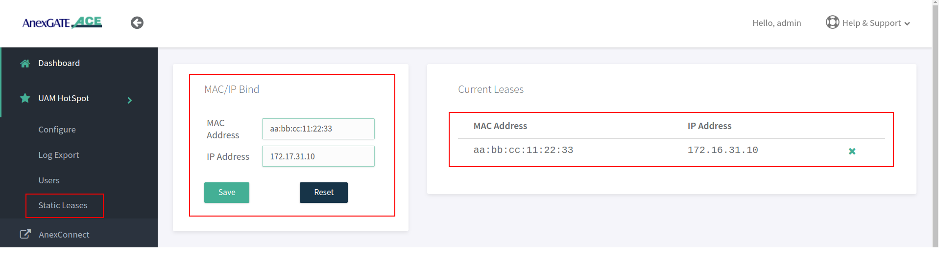
¶ UAM Hotspot Static Lease
Static IP and MAC address can be binded as a static lease under Static Leases.
To configure UAM HotSpot Static Leases, Go to UAM Hotspot - Static Leases.
NOTE:
- After mapping IP and mac under Static Lease, Re-save UAM Hotspot configuration by going to
UAM Hotspot - Configurein order for the Static Lease to be assigned as Static Lease under UAM Hotspot. - Static Lease are used for the user who needs the same IP address to be assigned whenever he connects to the UAM Hotspot network and has to add his/her credentials to be Authenticated.
Static LeaseandUAM MAC Address Bypassare two separate entities. Do not configure both Static Lease and add the same device MAC Address under UAM Mac Bypass.- Static Leases are used to bind IP address and MAC address for non-authenticated users. This show up as
Non Authenticatedusers under UAMUserswhen the UAM hotspot is configured. - Whereas, Assigning manual IP Address to the bypassed MAC Address under UAM Hotspot will bind IP and MAC address and show them as
Authenticatedunder UAMUserswhen the UAM hotspot is configured.
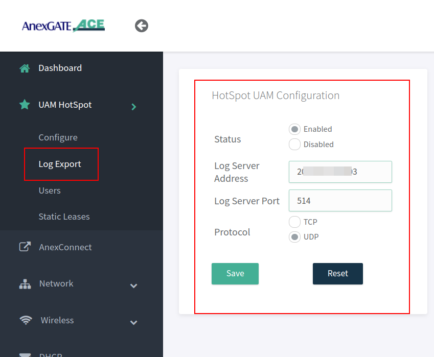
¶ Managing Syslog & UAM Logs Export
- Enable Log Export in order to export the logs from the authenticated users as well as other logs generated in the device to the mentioned Log Server to capture the traffic logs.
- To configure UAM Log Export, Go to
UAM Hotspot - Log Export.
Example - Log Server IP Ex: 2.12.16.23 is listening on UDP Port 514 for logs.
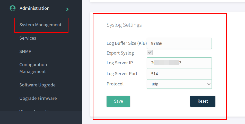
- After configuring the Log Export under UAM Hotspot. Go to
Administration - System Management - Syslog Settingsin order to export the logs to the mentioned Public IP address and port.
The Log Buffer Size (KiB) are to assigned as per AnexGATE Router models.
- ACE Classic Plus Gigabit V2 – Log Buffer Size (KiB) is 4888 KiB.
- USG ACE Series Model - Log Buffer Size (KiB) is 97656 KiB.
¶ TROUBLESHOOTING LOG EXPORT
If the logs are not being received at the Destination Log Server after mentioned in the Log Server Address under Administration - System Management.
- See if the Log Server Port Listening mentioned is TCP or UDP at both ACE device and Destination Server.
- The netcat command can be used in Linux Systems to troubleshoot and check if the ports are open.
At Destination Log Server, install netcat command
Type nc –l <port number> to listen on TCP port
Type nc –l –u <port number> to listen on UDP port
Example: nc –l –u 514
At Ace Side local network, install netcat in Linux machine.
• Type nc <ip address> <port number>
Example: nc 203.112.156.203 514
▪ If you are not able to see messages of one another sent/received on the netcat service then,
▪ Go to Administration - Services - Restart NAT Export Services.
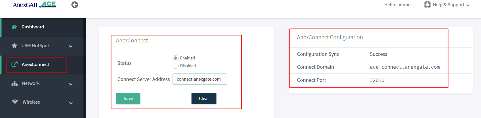
¶ AnexCONNECT
AnexCONNECT is a service which lets the user, monitor and control the status of the ACE Router as well as change the device configuration.
Follow these steps to enable AnexCONNECT under ACE Router.
- Add a valid
AnexCONNECT enabledlicense key by signing up at https://connect.anexgate.com - Once license key is added sucessfully in AnexCONNECT. In ACE router, go to
AnexCONNECTTab. - Enable AnexCONNECT and add Connect server address.
- Click on Save.
The AnexCONNECT configuration will show as Success once the connection has been established to AnexCONNECT server.
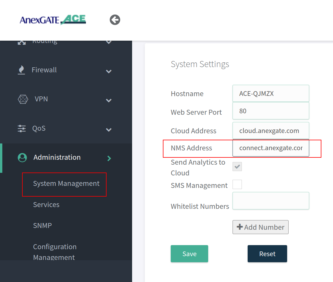
NOTE:
Configure the NMS address as connect.anexgate.com under Administration - System Management - System Settings beforehand to receive telemetry statistics of the router in AnexCONNECT portal.
¶ IPSEC
¶ IPSEC Configuration
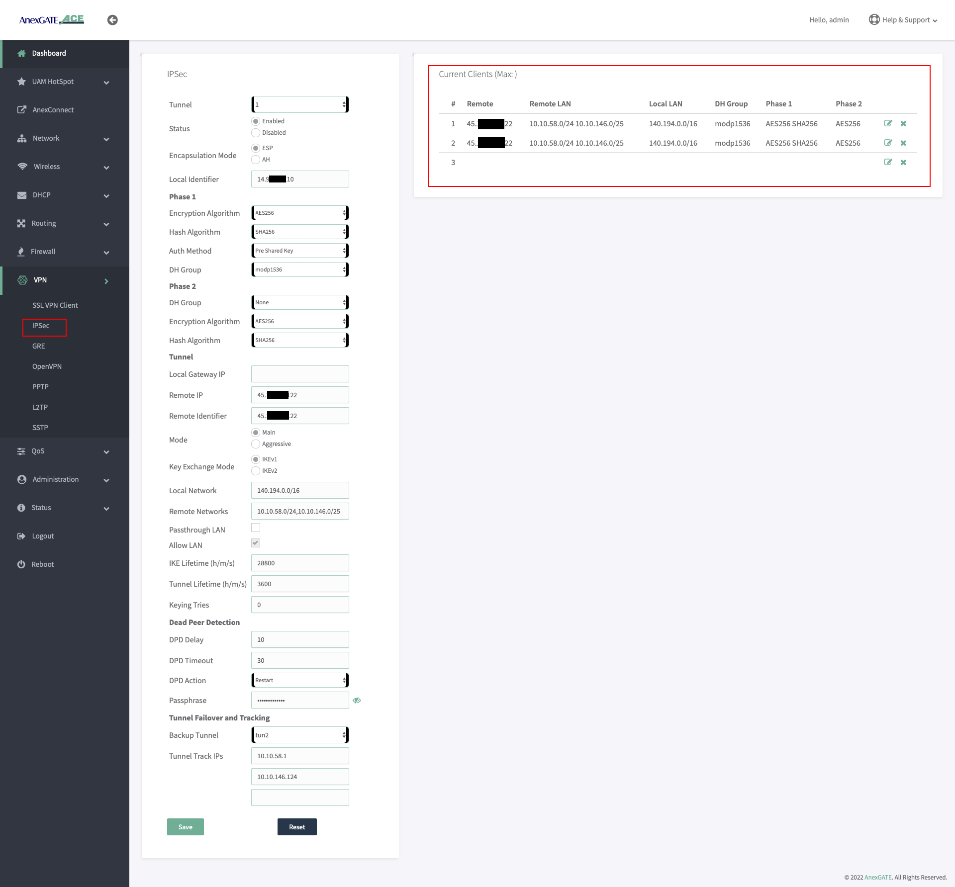
To configure IPSec, Go to VPN - IPSec and configure the parameters with respect to the configuration of IPSec at the remote side. Below are the parameters required for establishing the IPSEC Tunnel connectivity.
| Name | Description |
|---|---|
Tunnel |
Select IPSec Tunnel connection instance. |
Status |
Enable or Disable the IPSec Tunnel instance. |
Encapsulation Mode |
|
Local Identifier |
The Local Identifier is typically an IP address (123.123.123.1) or a hostname (ACEIPSEC) that identifies the local endpoint to its remote peer. |
| Phase 1 | |
Encryption Algorithm |
The encryption algorithm is used to secure the communication channel between the two IPsec peers. Select one (E.g.- AES-128). |
Hash Algorithm |
The hash algorithm is used to generate the hash value of the exchanged messages, ensuring message integrity and authenticity for Phase 1.. Select one from the drop down list. (E.g.- SHA1) |
Auth Method |
The authentication method is used to verify the identity of the IPsec peers during the key exchange process for Phase 1. The UAM Router supports Pre-shared Key as Authentication Method. |
DH Group |
The Diffie-Hellman group is used to generate the shared secret key between the IPsec peers for Phase 1. Select one from the drop down list. (E.g.- modp 1024. Also termed as DH - Group 2). |
| Phase 2 | |
DH Group |
The Diffie-Hellman group used to generate the shared secret key between the IPsec peers for Phase 2. Select one from the drop down list. (E.g.- modp 1024. Also termed as DH - Group 2). |
Encryption Algorithm |
The hash algorithm is used to generate the hash value of the exchanged messages, ensuring message integrity and authenticity for Phase 1.. Select one from the drop down list. (E.g.- SHA1) |
Hash Algorithm |
The authentication method is used to verify the identity of the IPsec peers during the key exchange process for Phase 1. The UAM Router supports Pre-shared Key as Authentication Method. |
| Tunnel | |
Local Gateway IP |
Specify the IP Address of the Local UAM Router Gateway. Leaving it blank, indicates that any available local interface can be used as Local Gateway. |
Remote IP |
Specify the IP Address of the remote device where the IPSec Tunnel has been configured. |
Remote Identifier |
Specify the identity of the remote gateway. Remote Identifier used is typically an IP address (123.123.123.1) or a hostname (RemoteIPSEC) that identifies the remote peer. |
Mode |
Select the mode for Key exchange.
|
Key Exchange Mode |
Specify the type of key exchange mode to use.
|
Local Network |
Specify the Local Network subnet that should be accessible through the VPN connection. E.g.- 192.168.10.0/24,172.16.0.1/20 ( Add network subnets separated by comma if multiple.) |
Remote Networks |
Specify the Remote Network subnet that should be accessible through the VPN connection. E.g.- 192.168.10.0/24,172.16.0.1/20 ( Add network subnets separated by comma if multiple.) |
Passthrough LAN |
Only enable this to establish an IPsec connection as a passthrough, allowing traffic to pass through the gateway without modification or encryption. (Not used in most cases.) |
Allow LAN |
Select this to forward the IPSec Traffic towards destination LAN and vice-versa. |
IKE Lifetime |
Specify the lifetime of the IKE (Internet Key Exchange) phase 1 key in seconds. |
Tunnel Lifetime |
Specify the lifetime of the IPsec phase 2 key in seconds. |
Keying tries |
The Keying tries parameter specifies how many times to attempt key exchange before giving up. The value set to ‘0’ means that key exchange will be attempted indefinitely. |
| Dead Peer Detection | |
DPD Delay |
The DPD Delay specifies the delay between sending DPD packets in seconds. |
DPD Timeout |
The DPD Timeout parameter specifies the amount of time to wait for a DPD response before considering the peer (remote IPSec) dead in seconds. |
DPD Action |
Dead Peer Detection (DPD) Actions in IPsec specify what action to take if a peer fails to respond to the DPD request message, used to detect if a remote peer is still available. Select the DPD Action as required from the below:
|
Passphrase |
When Pre Shared Key is selected as a mode of authentication. This secret shared key must be configured same between the IPSec Peers. |
| Tunnel Failover and Tracking | |
Backup Tunnel |
Select the secondary IPSec Tunnel as backup if there are multiple IPSec Tunnels configured.The IPSec Tunnel will failover to secondary IPSec connection when primary IPSec goes down. |
Tunnel Track IPs |
Enter the Tunnel Track IPs of Remote LAN network subnet to check the reachablility of the Remote peer. If the track ips fail to ping/reach the specfied remote peer IPs. The IPsec will try to re-establish continuously until the Tunnel Track IPs mentioned are reachable. |
NOTE:
- While configuring IPSec, Local LAN Subnet network must be the network subnet assigned to UAM Hotspot must be mentioned instead.
- The IPSec parameters for Phase 1 and Phase 2 configuration must be identical to the remote side IPSec parameters. If even one of the parameters is not identical then the IPSec tunnel will not get established.
IPSec failovercan be performed by configuring two IPSec tunnel and mentioning Backup Tunnel (Secondary) underTunnel failover and Tracking settings.Tunnel Track IPswill check the reachability towards remote destination LAN network hosts. If the IPs are not reachable then the IPSec tunnel will be re-established until the Host-IPs are pingable/reachable from the AnexGATE UAM Hotspot Router.
¶ IPSec Firewall Rule
Configure Firewall Zone for IPSec under Firewall - Rules and add remote LAN network and subnet. Configure NAT Forwarding as shown in the image.
¶ IPSec Zone
IPSec Zone must be configured under Firewall - Rules with Masquerading and MSS disabled.
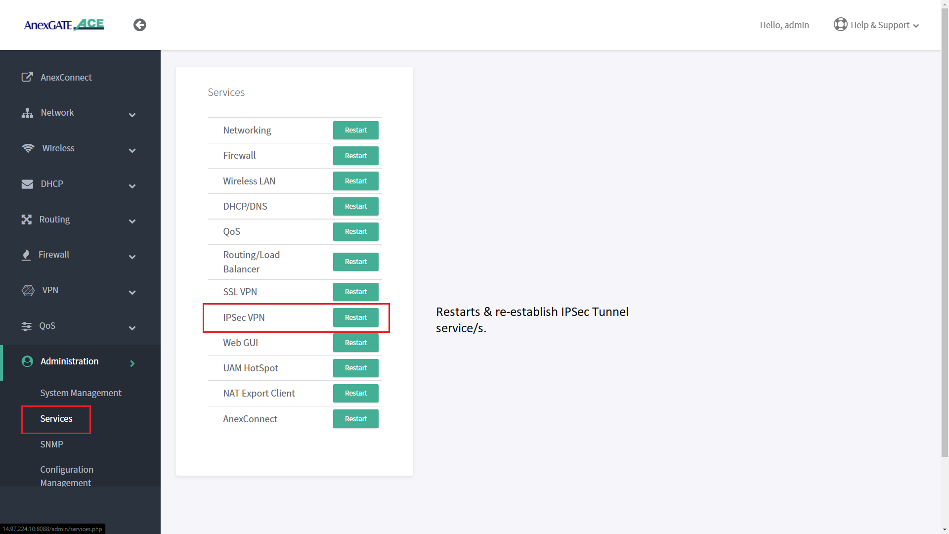
¶ IPSec Service
IPSec service can be restarted to re-establish tunnel if the remote side network subnet is unreachable. Go to Administration - Services - IPSec VPN . Click on Restart to restart the IPSec service.
¶ IPSec Status Log
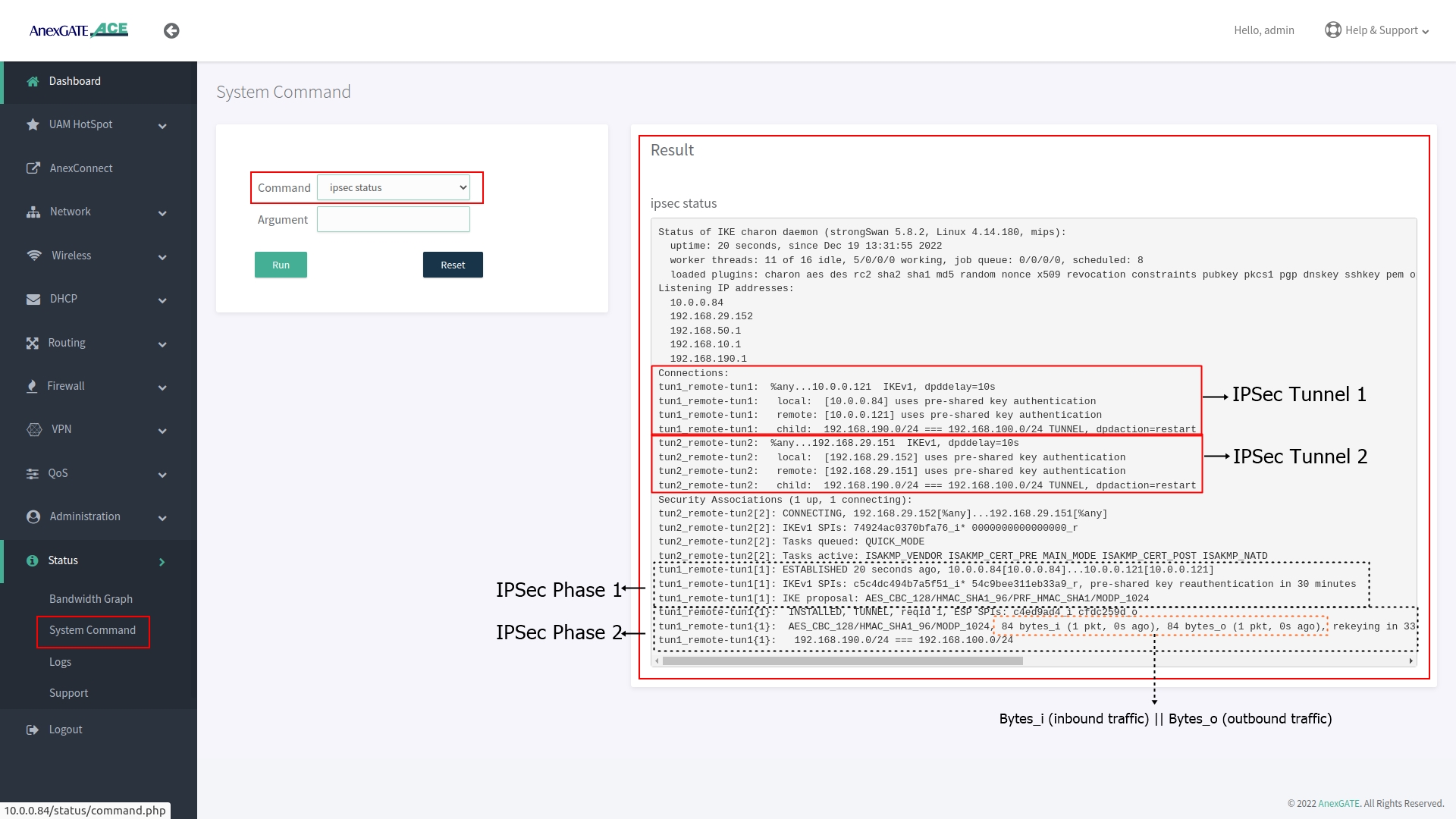
To check the IPSec status, Go to System Command and select IPSec Status from drop down list and click Run.
The output is shown below displays the IPSec Phase 1 being established 3 hours ago with respective remote IPSec Network and under Phase 2 is the IPsec tunnel where data is being inbound and outbound connected to their assigned LAN Network subnet.
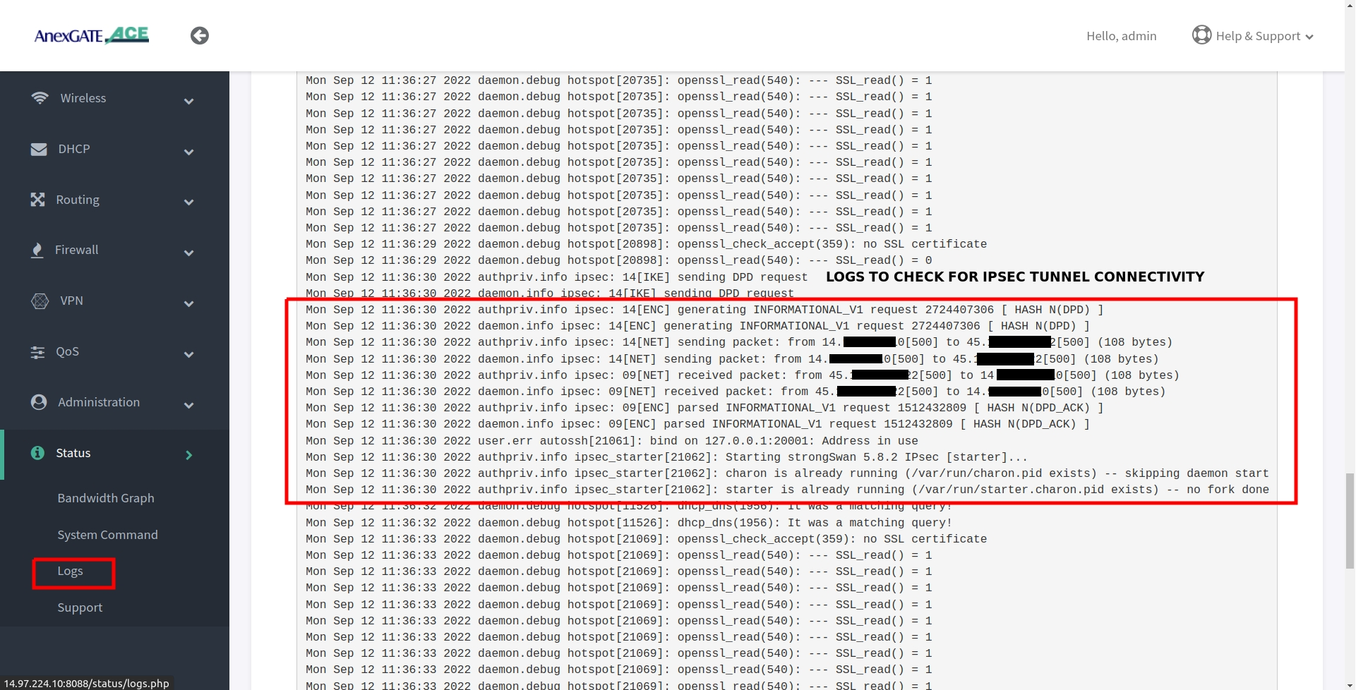
¶ IPSec Connectivity Logs
IPSec logs can be viewed under Status - Logs. In order to view the log from beginning of the IPSec Tunnel, the IPSec service must be restarted by going to Administration - Services and restarting IPSec Service, then go to Status - Logs
¶ TROUBLESHOOT IPSEC CONNECTIVITY
- Re-check and compare IPSec Parameters configured at both local and remote side.
- Check Firewall zone for IPSec and remote lan subnet have been configured.
- Check ipsec status by going in
Status - System Command - IPSec Status. - Under IPSec status check if IPSec Phase 2 has been established and traffic inbound and outbound. (Refer IPSec status log for more information)
- Check reachability of WAN IP where IPSec has been configured.
- Check pinging the Remote LAN network gateway.
- Check IPSec logs in
Status - Logs.
¶ Administration
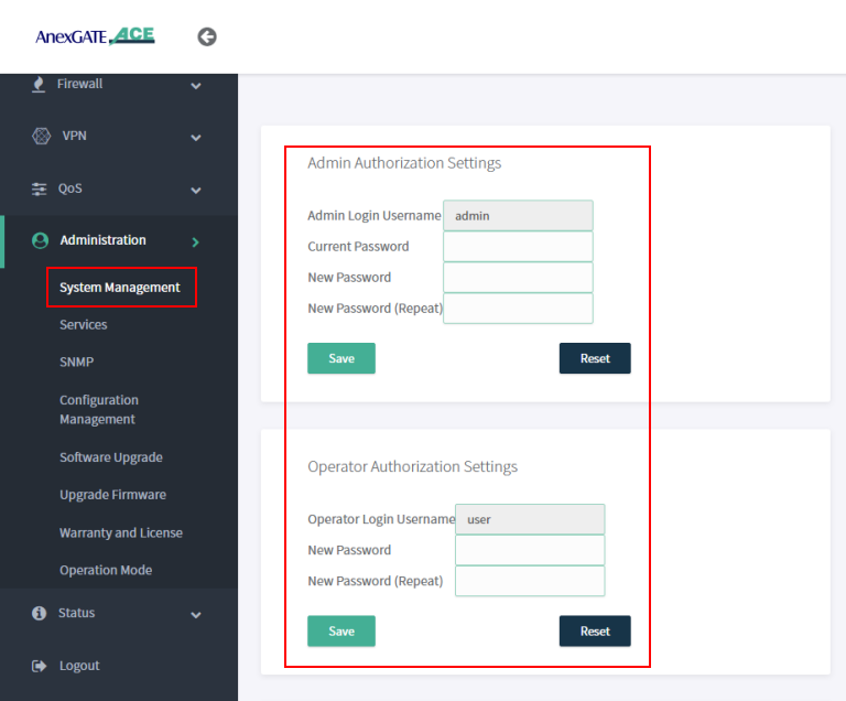
¶ System Management
Under System Management, Admin and User password can be changed by entering the current default password and add new password.
NOTE:
User/Operator mode can be used for monitoring and diagnosis of the network and router. When using user credentials, if any changes are done in the router configuration, the user will logout immediately without reflecting any changes in the router.
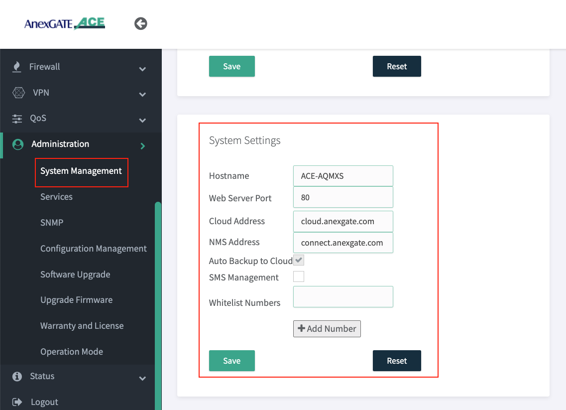
¶ System Settings
Under Administration - System Management - System Settings Hostname of the router and Web Server Port to access the ACE Router can be changed.
NOTE:
- Go to
Administration - Serviceand RestartWEBGUI Serviceafter changing Dashboard Port. - Change NMS Address as
connect.anexgate.comfor AnexCONNECT.
¶ Syslog Settings
Syslog must be configured in the ACE Hotspot router in order to receive device logs as well as NAT Logs of connected users to UAM hotspot.
To configure syslog settings,
Go to Administration - System Management - Syslog Settings in order to export the logs to the mentioned Public IP address and port.
NOTE:
The log buffer Size for USG model and ACE model is as follows:
- USG Series Model =
97656 KiB - ACE Classic Plus Gigabit V2 =
4888 KiB
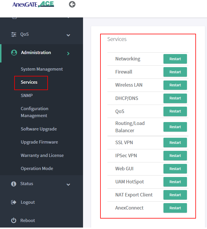
¶ Services
Under Administration - Services, each service running on the AnexGATE HotSpot router can be restarted without rebooting the device if a particular service is not functioning properly.
Also, it is useful when you do any changes in the router. It is recommended to restart the UAM Hotspot service for it to function as expected.
Services used for AnexGATE HotSpot are as follows:
| Service | Description |
|---|---|
Networking |
Restart LAN/WAN Service. |
Firewall |
Restart Firewall Services like Zone, Rules and NAT Forward. |
Wireless LAN |
Restart Wireless LAN Service. |
Routing/Load Balance |
Restart Load Balancing Service. |
SSL VPN |
Restart SSL VPN Tunnel Service. |
IPSec VPN |
Restart IPSec Tunnel Service. |
Web GUI |
Restart Dashboard Service. |
UAM Hotspot |
Restart UAM HotSpot Service. |
NAT Export Client |
Restart UAM Export Service. |
AnexConnect |
Restart AnexCONNECT Service. |
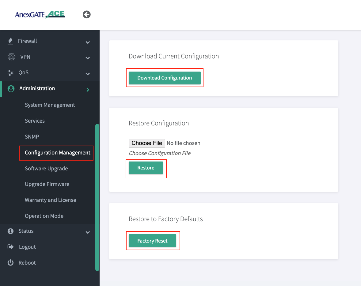
¶ Configuration Management
The UAM Router provides the ability to back-up the existing configuration manually and restore the configuration for the same respective UAM router.
¶ Download Configuration
To download the current existing configuration of the UAM Router, Go to Configuration Management, click on Download Configuration.
¶ Restore Configuration
The UAM Router back-up configuration downloaded, can be later restored to the same UAM Router by clicking on choose file and selecting the backupxxxxx.bin that is exclusive to that particular UAM router and click on Restore.
Once the router configuration has been restored. Reboot the UAM router for the services to take effect.
¶ Factory Reset
The UAM router can be software resetted to initial state with default configuration. To reset the UAM router, go to Administration - Configuration Management - Factory Reset Click on Factory Reset.
Once the factory reset is performed, reboot the UAM router for the services to take effect.
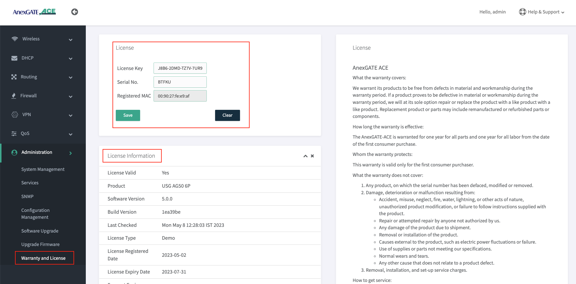
¶ Warranty and License
The Warranty and License section provides the License status and information of the UAM router. The License is only valid to its respective Router.
To register a License key, Go to Administration - Warranty License or click on View License Details tab and enter the License Key issued for that respective UAM Router.
NOTE:
- The License Key will be removed from the UAM Router if software/hardware(Ace-Gigabit) Reset has been performed or wrong license has been added in the UAM router.
- It is mandatory to have the valid License Key during the deployment of the UAM Router. If there is no License Key being shown. Contact the support to issue the License for that respective router. The License Key can be inserted by clicking on View License details which redirects to
Administration - Warranty and Licensepage if the Hardware or Software reset is performed on the UAM Router. - The LAN users will not have access to internet until and unless the license has been properly saved and validated under Warranty and License page once the
License keyhas been saved. - Before saving the License Key. Check if the router is able to access internet by going to
Status - System Commandandping google.com. Once the domain is pingable, Save the License Key. - License keys are unique to their respective UAM Routers. Make sure the proper License key is inserted. Failing to do so, the status of License key will appear as
Not Validcausing the LAN users to not have access to the internet.
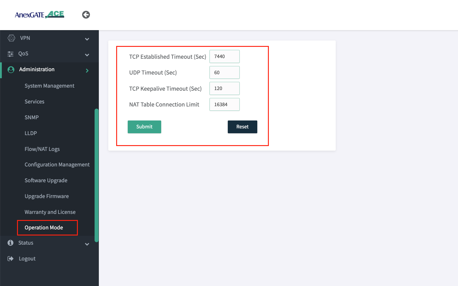
¶ Operation Mode
| Name | Description |
|---|---|
TCP Established Timeout (Sec) |
Assign the timeout duration for established TCP connections. Default = 7440 seconds. |
UDP Timeout (Sec) |
Assign the timeout duration for UDP connections. Default = 60 seconds. |
TCP Keepalive Timeout (Sec) |
Assign the time for sending TCP keepalive probes to ensure the connection is still active. Default = 120 seconds. |
Max Connections |
Set the maximum number of tracked connections allowed intiated by the UAM router. Default = 16384 connections. 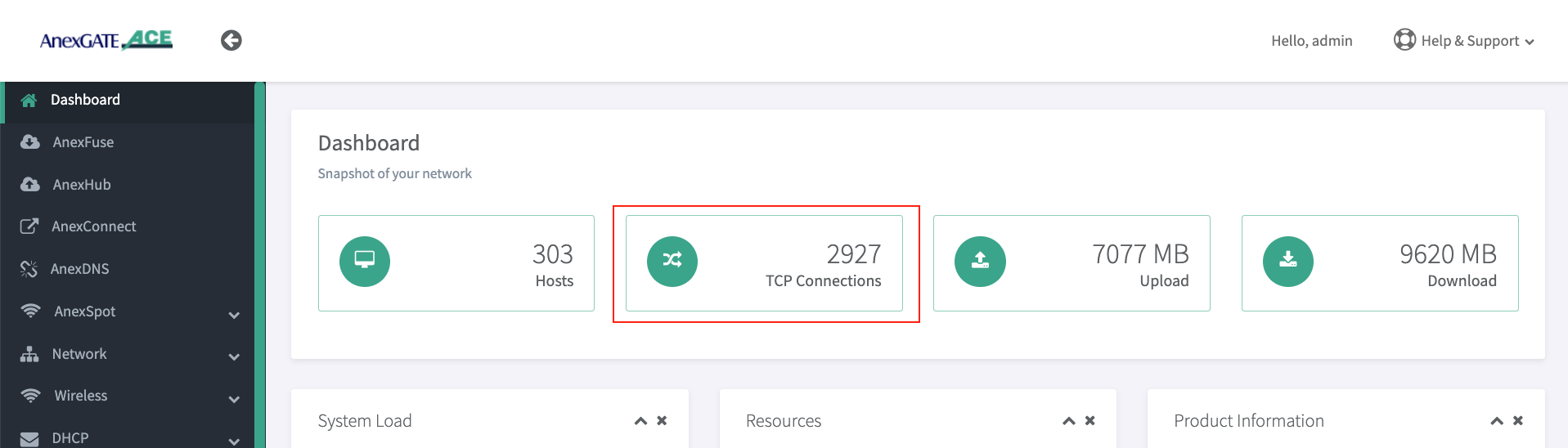 IMPORTANT NOTE: If there are large number of users authenticated in the UAM Hotspot network and are facing slow network issue, check the Dashboard for Max/TCP Connections. If it is displaying 16384 connections active already. Increase the number of Max Connections allowed accordingly which can be assigned upto 65534 under |
¶ Status
¶ Checking UAM Router Status and Logs
Network Status and Logs allows the user to carry out Diagnostic operations over the AnexGATE Router.
The Diagnostic tools under UAM Router are as follows:
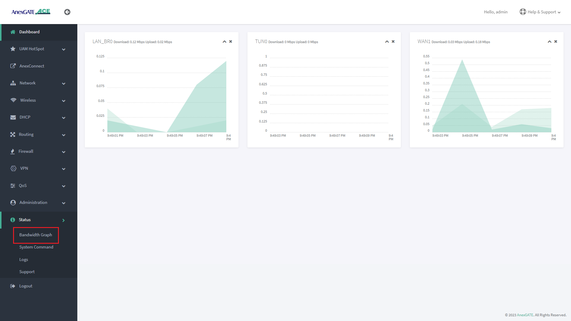
¶ Bandwidth Graph
Bandwidth Graph displays a live graphical Representation of the traffic flowing through the Interfaces configured on the ACE Router. It displays the graph of Inbound/Outbound Traffic on each Interfaces.
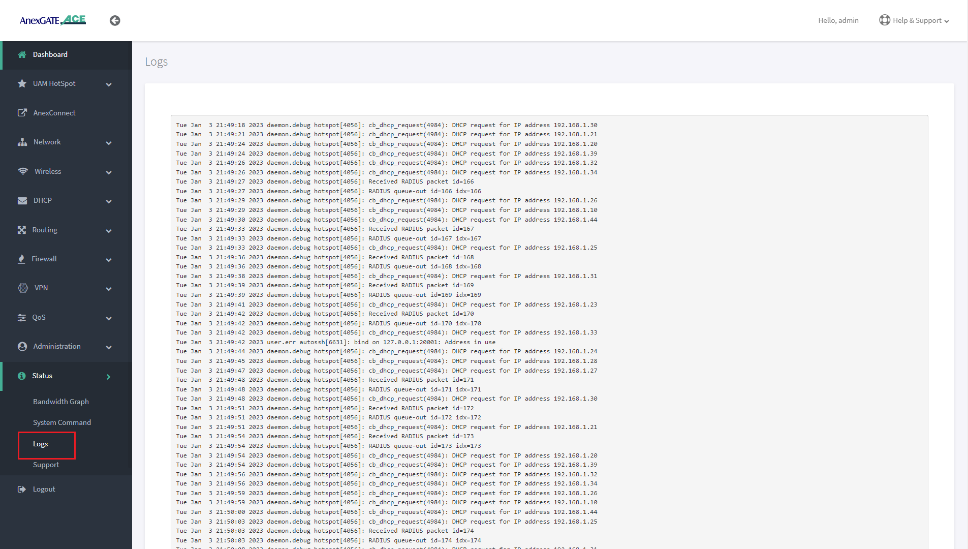
¶ Logs
Device or System Logs can be viewed at Status - Logs. The logs are stored temporarily and rotate as per Log buffer size assigned in the router.
NOTE:
The logs will be cleared after device reboot.
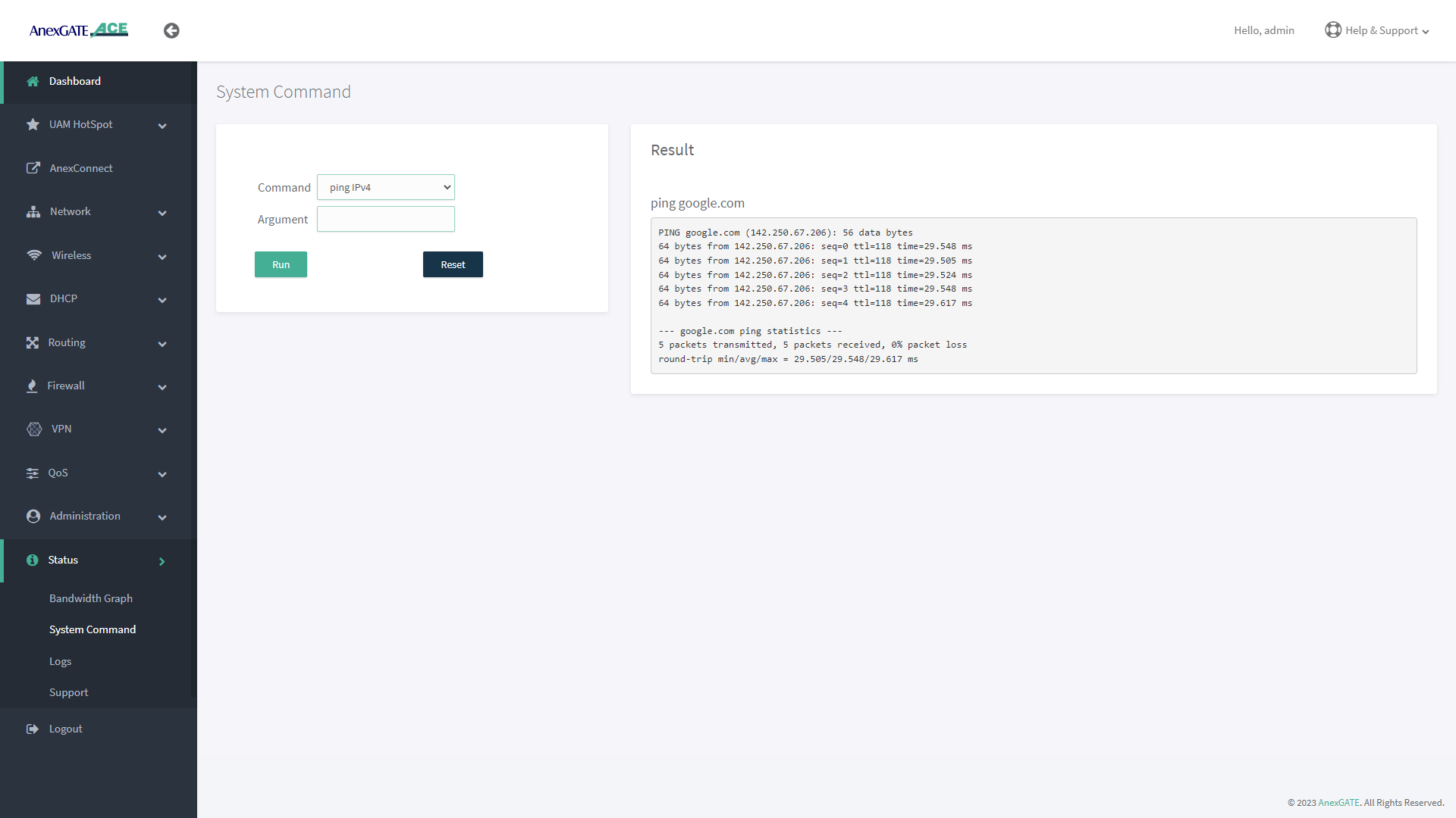
¶ System Command
System command are set of Commands useful for diagnosing the AnexGATE Hotspot Router, as well as troubleshooting the connectivity problems.
| Command | Argument | Description |
|---|---|---|
ping ipv4 |
<domain / ip address> Ex: Ex: |
Checks the reachability to the Domain or IP. |
|
<domain / ip address> -I <interface> Ex: Ex: |
Checks the reachability to the Domain or IP address on a particular interface. Interface = eth1, eth2, eth3 eth0.2, eth0.3 ( Interfaces for ACE Classic Plus Giga)etc.. |
|
ifconfig |
**no argument** | Displays ‘active’ interface configuration. |
| -a | Displays interface configuration along with ‘inactive’ interfaces. | |
lsusb |
**no argument** | Displays information about USB buses in the system and the devices connected to them. |
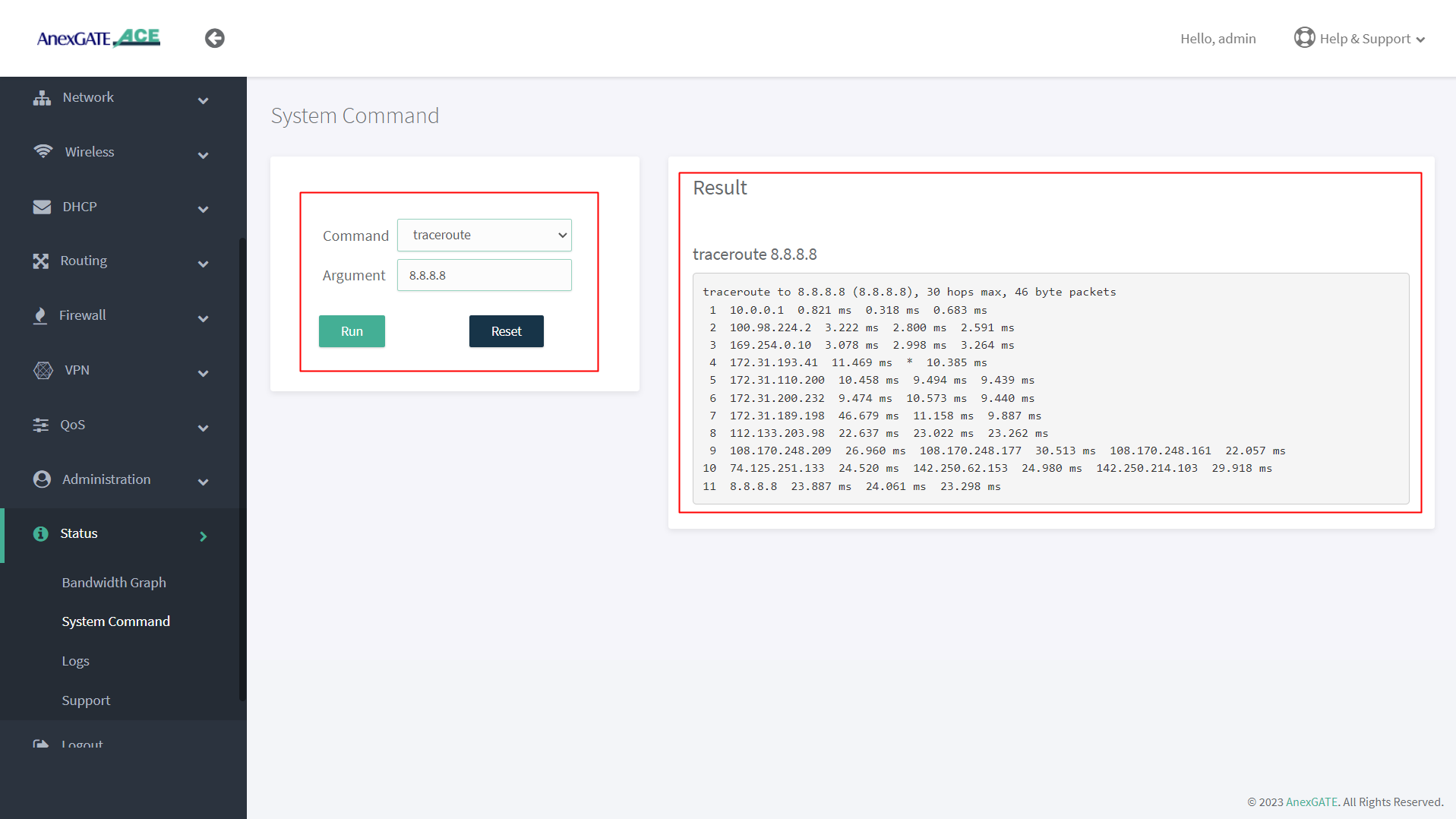
traceroute |
<domain or ip address> Ex: Ex: |
Displays the route that a packet takes to reach the host. Useful, when you want to know about the route and about all the hops that a packet takes. |
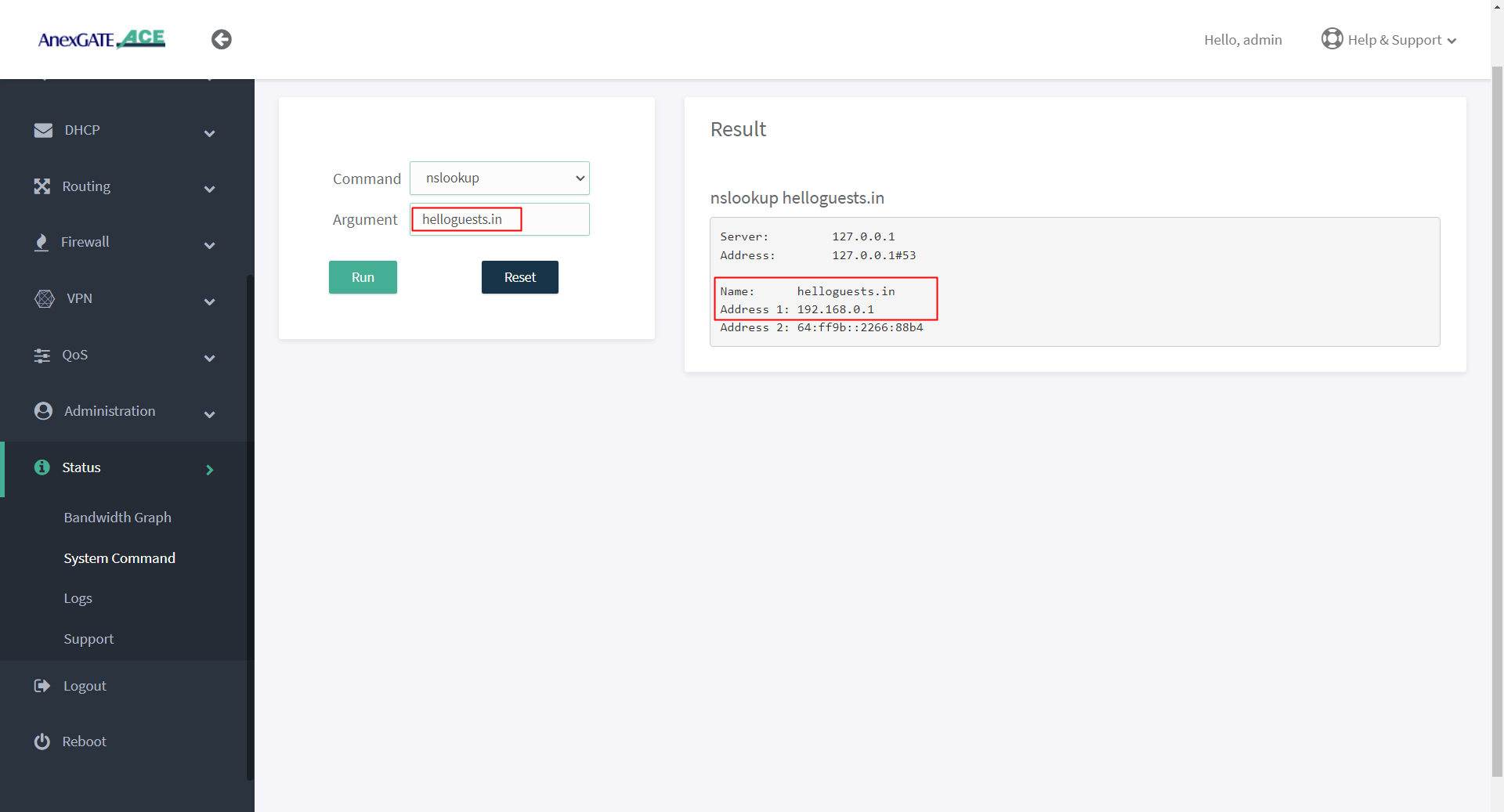
nslookup |
<domain or ip address> Ex: Ex: |
Displays “A record” (IP Address) of the domain and vice-versa. Use this command to find the address record for a domain. It queries to domain name servers and get the details. |
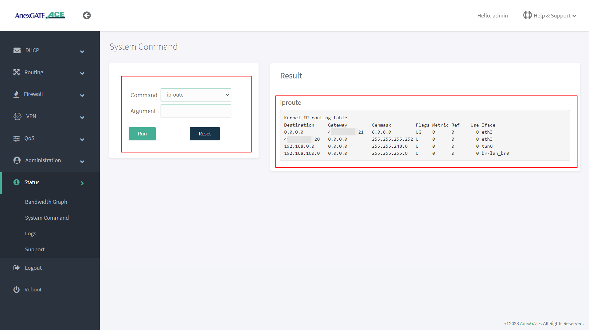
ip route |
**no argument** | Displays IP routing table. |
ipsec status |
**no argument** | Displays detail verbose output the IPSec Tunnel connectivity status. |
¶ PING Output
¶ IFCONFIG Output
¶ TRACEROUTE Output
¶ NSLOOKUP Output
¶ IPROUTE Output
¶ Device Logs
Status Logs of the Device can be viewed under Status - Logs.
Some of the Basic Logs have been shown below as reference to troubleshoot.
NOTE - Logs other than what have been displayed here and UAM Logs are only to be considered for Troubleshooting.
¶ Logs for ACE AWP and above Models
¶ WAN/LAN Link UP / DOWN
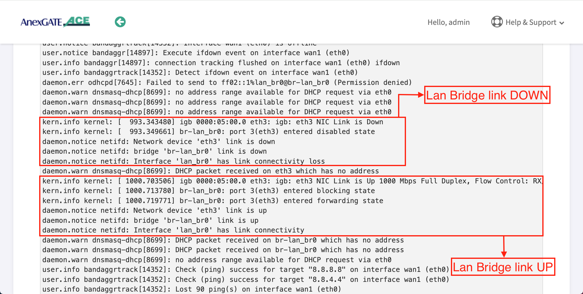
¶ LAN Bridge Link UP/DOWN
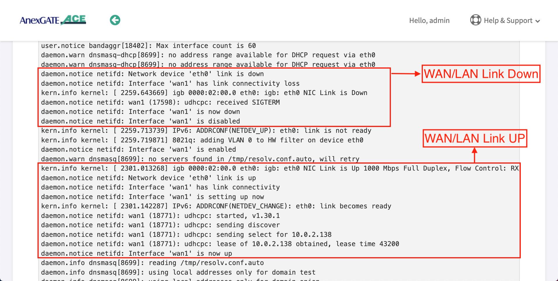
¶ Logs for ACE Gigabit v2 Model
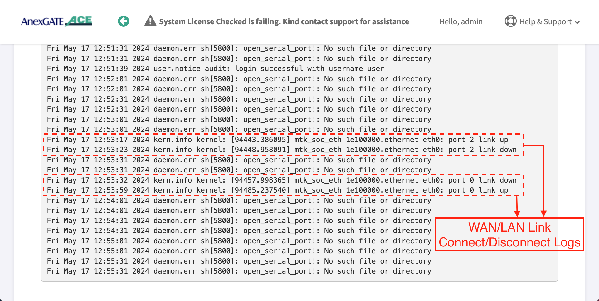
¶ WAN/LAN Link UP/DOWN
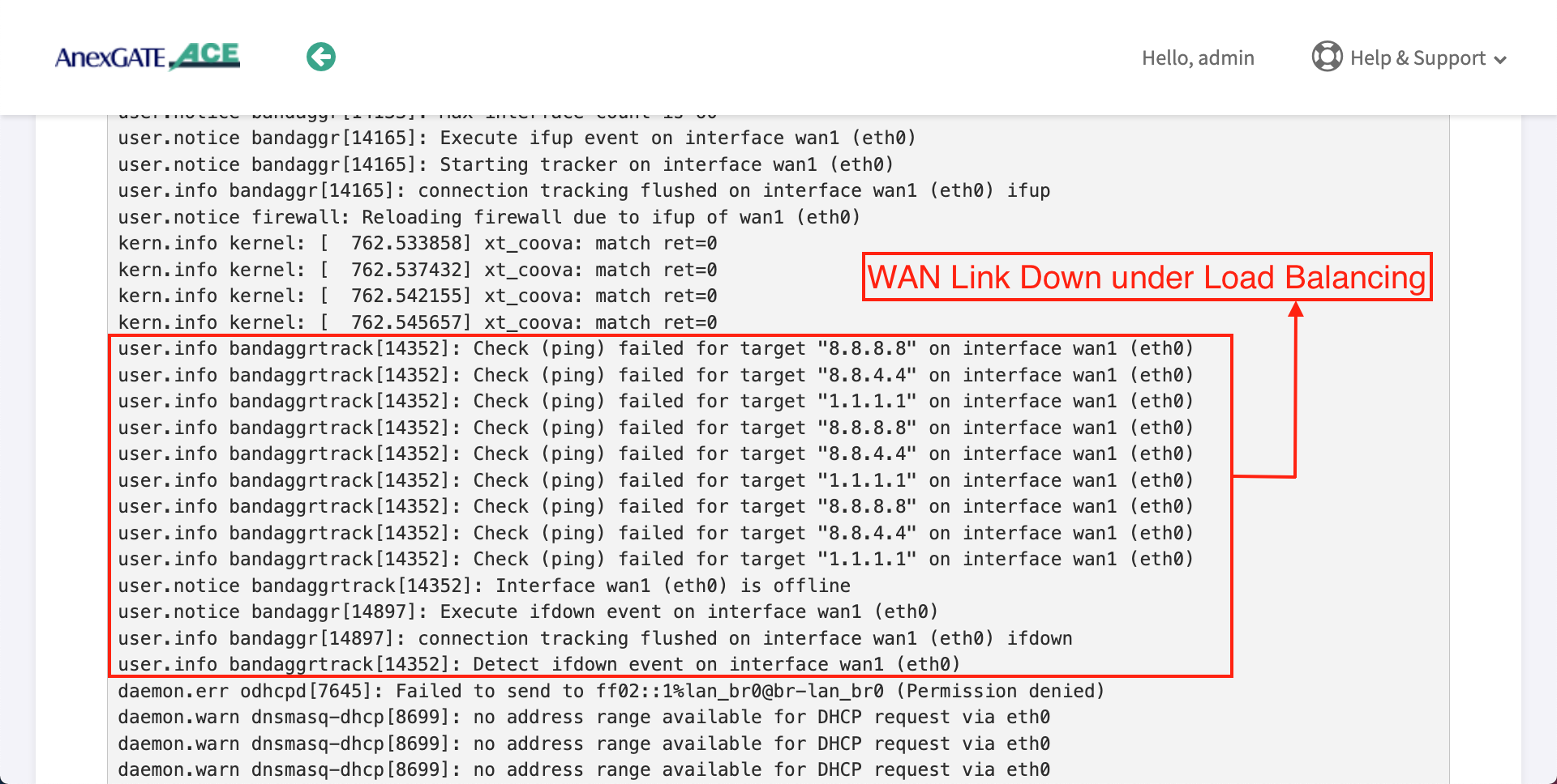
¶ WAN Link DOWN under Load Balancing
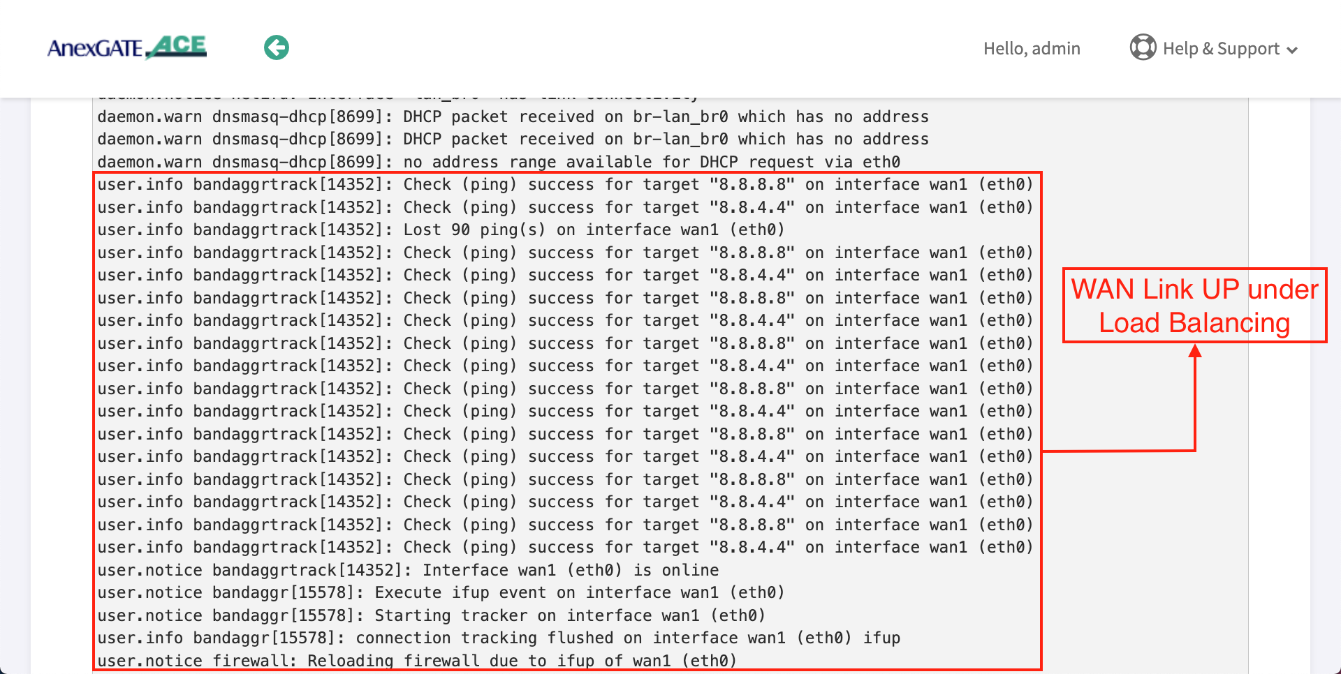
¶ WAN Link UP under Load Balancing
¶ IPSEC Connectivity Logs
¶ Troubleshooting AnexGATE Router and UAM Hotspot Issues
| Problem | Troubleshooting |
|---|---|
| Not able to ping or access the AnexGATE Router Dashboard |
OR
|
| Not able to connect to AnexGATE HotSpot |
|
| No HotSpot Login Page after receiving IP via DHCP |
|
| LAN/WAN Connectivity Issues |
|
| Multiple WAN Links Configured but no Internet when pinged |
|
| Unable to Login or Logout HotSpot Session in Laptop/Mobile |
|
| Unable to get DHCP IP or ping Hotspot gateway on configured VLAN |
|
| Some users are not able to get IP from UAM Hotspot DHCP server or Hotspot Login Page |
|
|
Dashboard Displaying Notification as “System Check is Failing. Kindly contact support for Assistance” |
|
¶ Disable DNS over HTTPs for LAPTOP and MOBILE
¶ For Laptop/Desktop -
Go to,
https://www.tenforums.com/tutorials/145372-how-enable-disable-dns-over-https-doh-google-chrome.html
https://support.unlocator.com/article/365-how-to-disable-dns-over-https-on-firefox-and-google-chrome-browsers
or
Follow these steps:
- Launch Chrome Web Browser in Laptop or Desktop.
- Select the three-dot icon and choose "Settings"
- On the settings screen, Type "secure DNS" in search settings
- Under Security and privacy, go to "Use secure DNS"
- Under Secure DNS, Turn off the Secure DNS.
- Close the browser.
- Turn OFF and turn ON the Network adapter/WiFi.
¶ For Mobile
Go to,
https://www.ceofix.net/2867/enable-secure-dns-doh-on-chrome-android/
or
Follow these steps:
- Launch Chrome Web Browser in Android Device.
- Select the three-dot icon and choose "Settings"
- On the settings screen, Tap on Privacy
- Tap on Use secure DNS under Privacy section
- Under Secure DNS, Turn off the Secure DNS.
- Close the browser.
- Turn OFF and turn ON the Network adapter/WiFi.
¶ Ports under AnexGATE HOTSPOT
Following ports must be open on the user's Internet upstream Router in order for UAM Hotspot to operate without any issues.
| Description | Ports |
|---|---|
| RADIUS Authentication | 1812 |
| RADIUS Accounting | 1813 |
| HTTPs Server Redirection | 8000 |
| Log Export | 514 |
| UAM Hotspot AAA Server | 3990 |
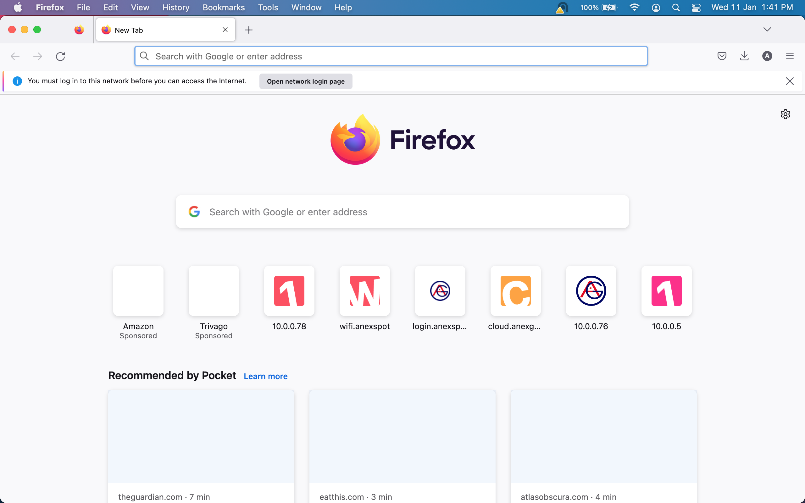
¶ Download Firefox
Firefox Browser has an ability to trigger captive portal manually by clicking on Open Network Login Page.
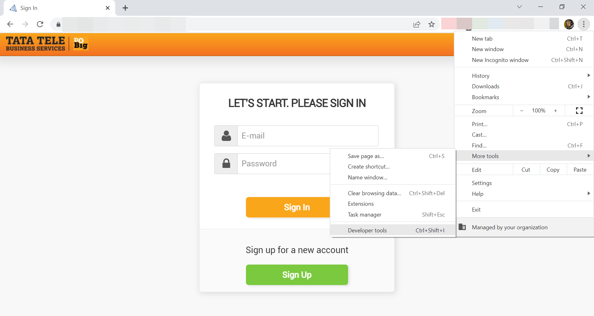
¶ Capture Web Session traffic and save as HAR file
- On a Hotspot Login Page. Open a browser
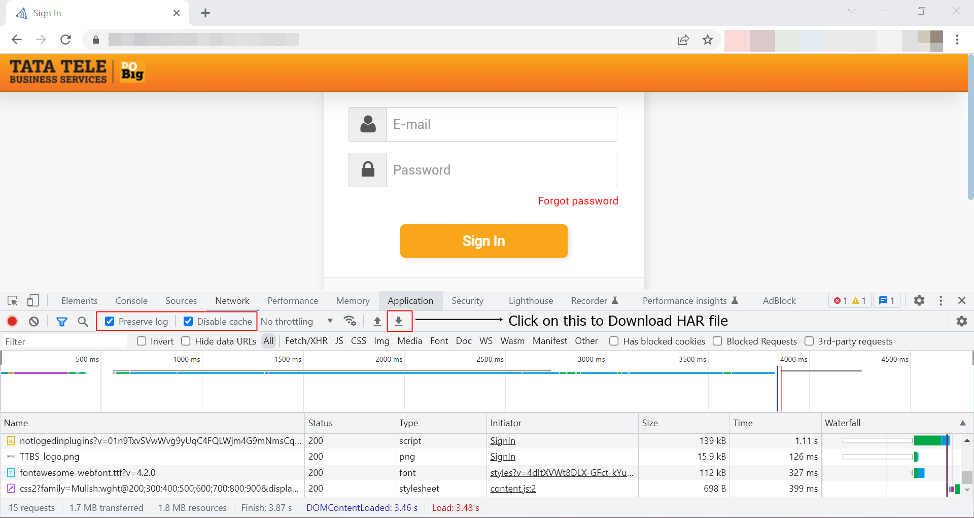
Press F12or Right click and select Inspect ElementorGo to Browser settings - More tools - Developer Tools.- Select Network, press Ctrl + R or Click Reload in Inspect Element Box.
- Enable preserve logs and disable cache.
- Save the activity logs from start of Login till the Logout in a file in the form of HAR file by pressing Import or save HAR File as shown.
- Click on this link for more information.
- Once the Logs are captured, Click on Import HAR File icon to download the file as shown in the image.
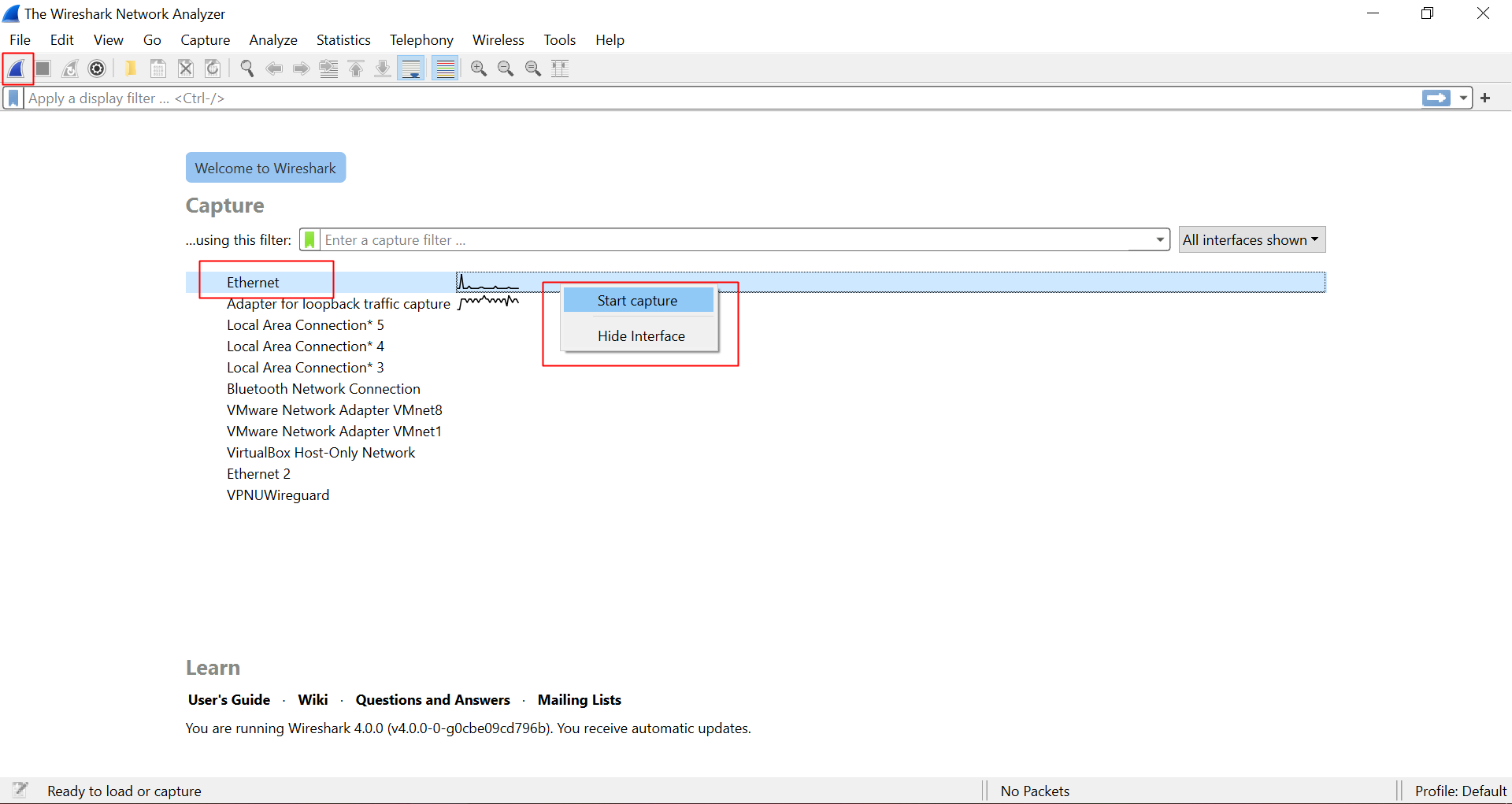
¶ Capture Network Packets using Wireshark
- Download and Install Wireshark
- Right click on Wireshark and Run as Administrator.
- Select the network adapter interface on which the hotspot network is connected, Click on Blue Icon or Right click on the network interface and click start capture.
- Once done with the capturing the network packets. To Stop wireshark packet capture, click RED stop button icon.
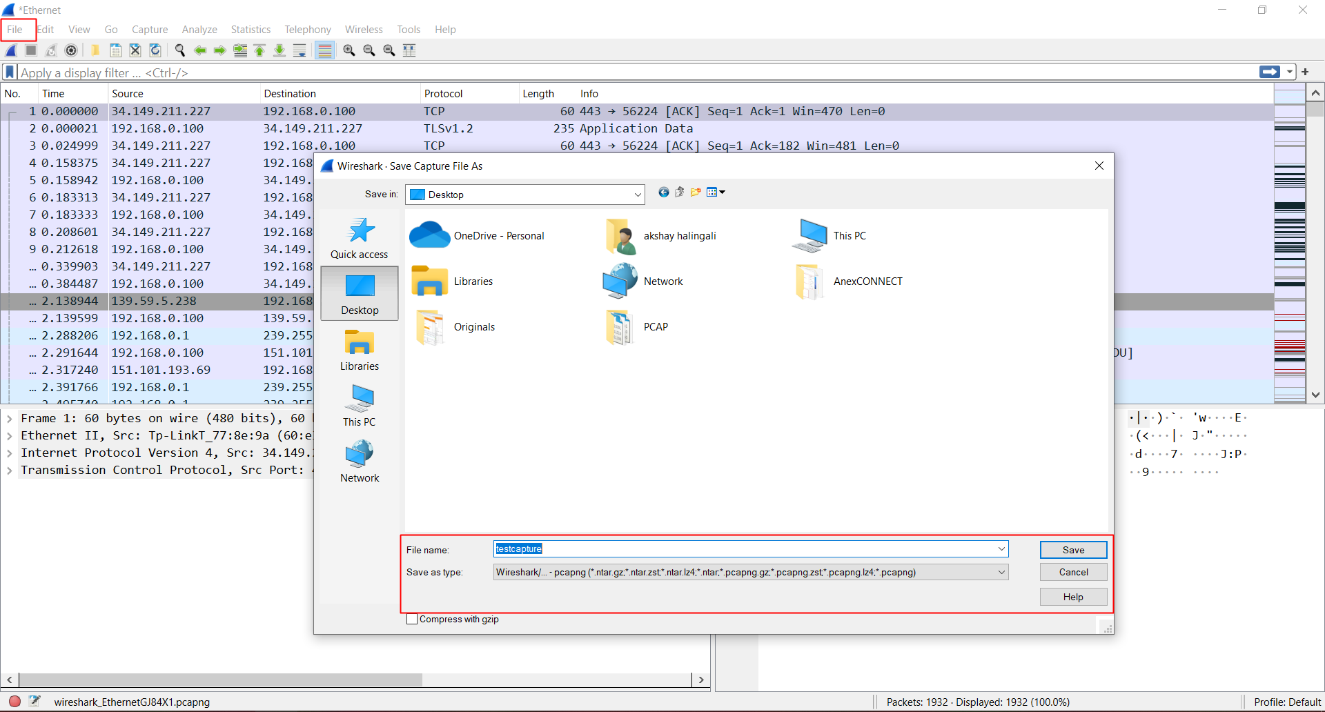
- Go to File and click on save to save the current packets captured.
- To start the capture again, click on the first Blue Shark Fin icon.
For more information about Wireshark menu toolbar, click on this link.
- Click on Red Stop button icon to stop packet capture.
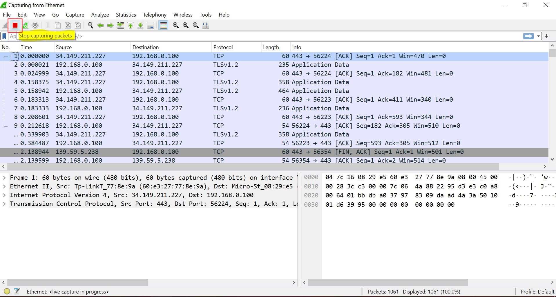
- Go to
File - SAVEor pressCtrl + sto save the network packet capture.
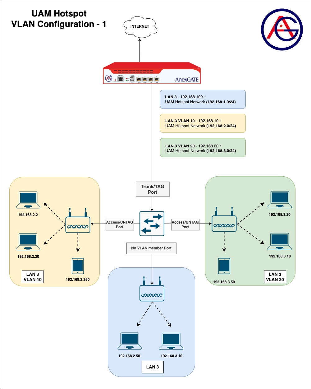
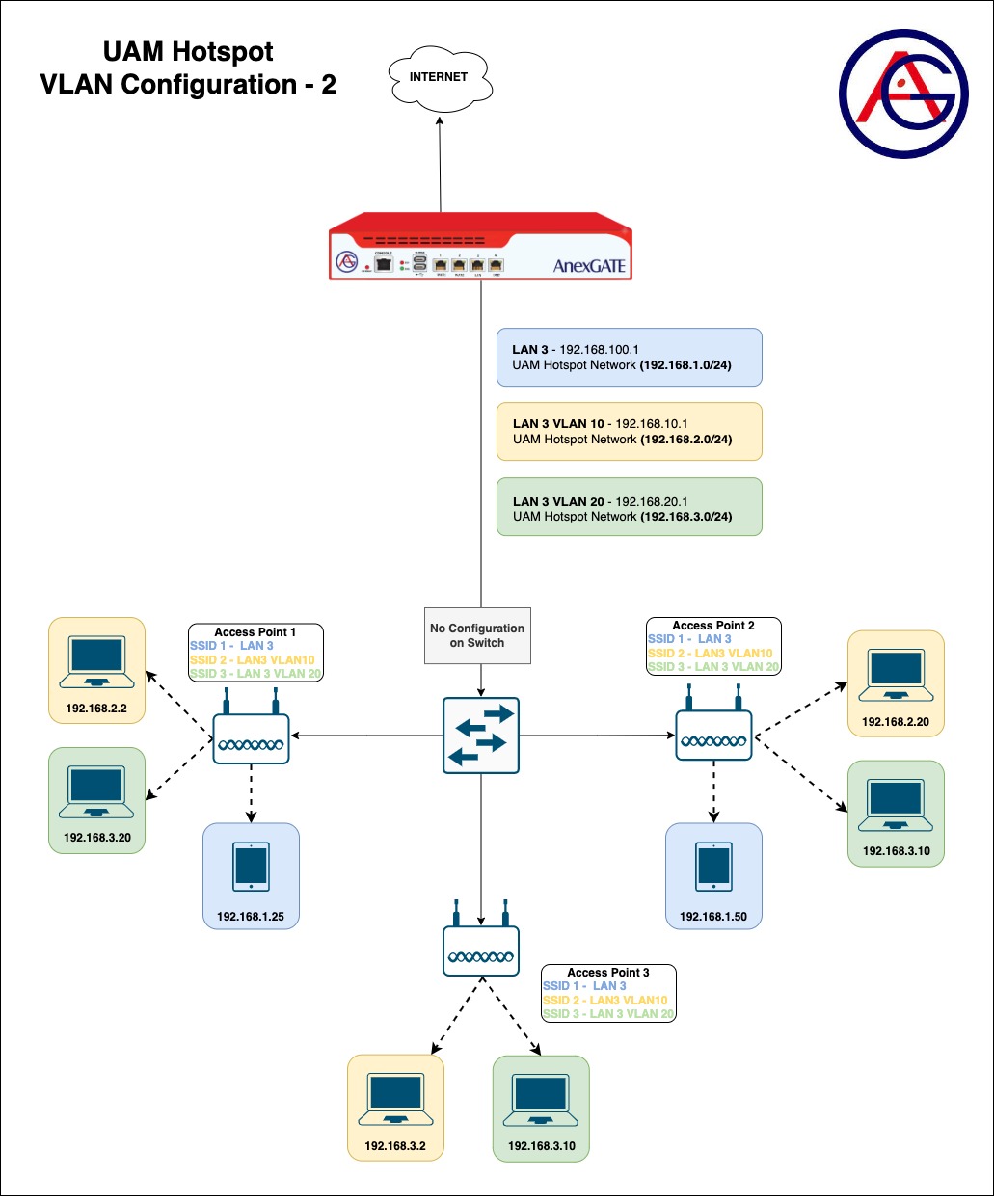
¶ SCENARIOS
¶ UAM ROUTER VLAN CONFIGURATION
.jpg)
¶ ACE UAM ROUTER PACKET FLOW
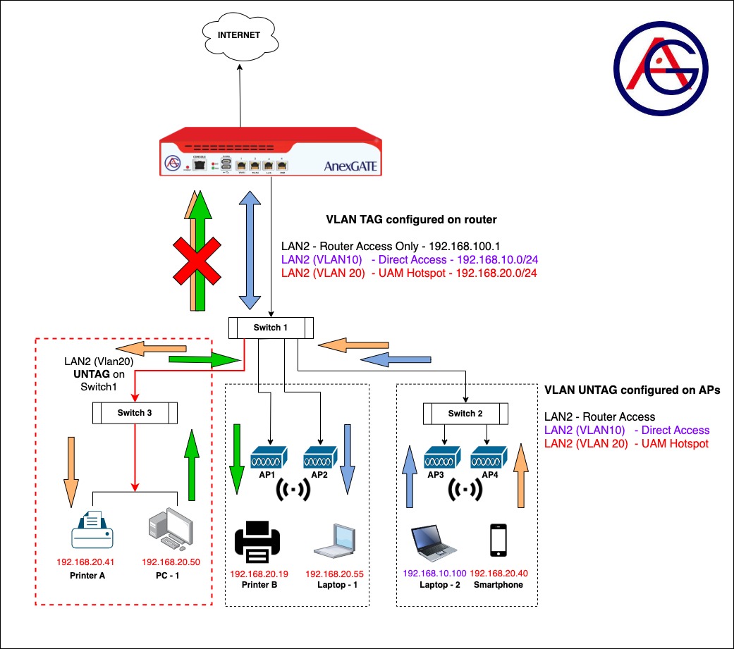
¶ Requirements:
- UAM Router
LAN & VLAN are to be configured on a single port of a UAM router. UAM Hotspot is then to be configured on its respective VLAN interface.
- Core Switch-1
Two Access Layer switches and Access Points 1&2 are connected. Some ports on the core switch are tagged to forward all traffic towards Switch-2. Connected Access Points VLAN 10 & VLAN 20 are untagged. One Port is configured as untagged which is connected to Switch-3.
- Access Layer Switch-2
Access Points 3&4 are connected. VLAN 10 & VLAN 20 are untagged under the Access Points.
- Access Layer Switch-3
VLAN 20 is untagged on Core Switch-1 Port. LAN devices are connected.
¶ Configuration of UAM Router:
- Connect the UAM router using default LAN or Static WAN 10.10.0.10 on Port 4 (recommended).
- Configure WAN interface. Assign metric(1,2,3) if multiple WAN links are being configured. Add the WAN interfaces under WAN Zone. Configure Load Balancing.
- Configure LAN interface on any Port of the UAM Router under LAN/WAN for access to the UAM Router if creating VLANs. Example: Interface
LAN2.
UAM Router has a default lan_br0 interface configured on Port 3. VLAN cannot be configured under Lan Bridge on lan_br0. Hence, configure LAN under LAN/WAN section by connecting Laptop via Static WAN IP 10.10.0.10 of the UAM router and remove the Lan Bridge lan_br0 if necessary.
- Configure Vlans on LAN interface under WAN/LAN and assign unique private network subnets on each interfaces.
Example: On LAN2, Configure
VLAN 10 LAN2_10 - 192.168.10.1/24
VLAN 20 LAN2_20 - 192.168.1.1/24
- Configure UAM Hotspot on VLAN 20
LAN2_20with its own network subnet (E.g.192.168.20.1/24).
NOTE:
UAM Network subnet should not overlap with any network subnets configured on the ACE UAM Router.
- Under
Firewall - RulesConfigure LAN Zone and add the interfaces in their respective LAN zones if multiple Hotspot and non Hotspot LAN are being configured.
Example: Create a separate LAN zone for UAM Hotspot and name it as Hotspot or hslan.
- Create appropriate NAT Forwarding rules to have the network traffic of two different lan segments forwarded between each other and establish the communication.
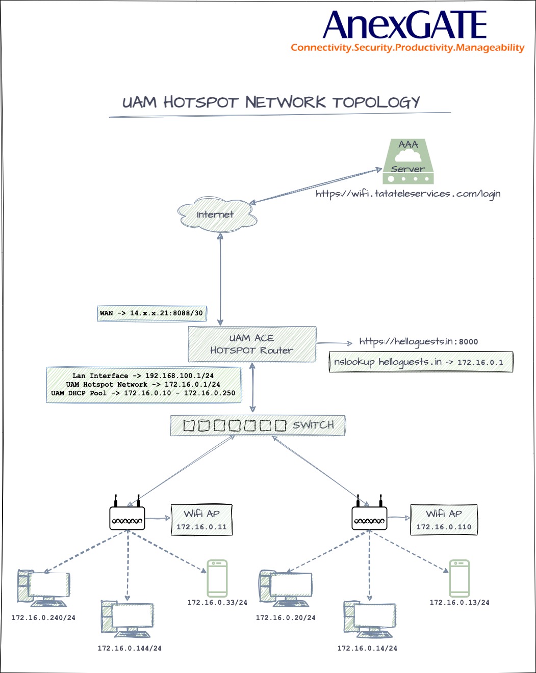
¶ Verifying Reachability through Packet Flow:
- Smartphone connected on AP under Switch 2 wants to reach a Printer connected in Switch 3 to print a page.
Packet Flow - Smartphone (IP: 192.168.20.40) → Access Point → Switch-2 → Switch-1 → Switch-3 → Access Point → Printer (IP: 192.168.20.41).
NOTE:
The packet does not reach the UAM router since the destination IP Address is under same network segment with /24 subnet as Source IP Address.
- PC-1 Connected under Switch 3 wants to communicate with the printer under Switch 1.
Packet Flow - PC-1 (IP: 192.168.20.50) → Access Point → Switch-3 → Switch-1 → Access Point → Printer (IP: 192.168.20.19).
NOTE:
The packet does not reach the UAM Router since both Source IP Address and the destination IP Address is under same network segment with /24 subnet.
- Laptop-2 connected under Switch 2 sends a ping request to Laptop-1 under Switch 1.
Packet Flow - Laptop-2 (IP: 192.168.10.100) → Access Point → Switch 2 → Switch 1 (VLAN10) → UAM Router: LAN2_10 → LAN2_20(hspt tun0) → Switch 1 (VLAN20) → Access Point → Laptop-1 (IP: 192.168.20.55).
NOTE:
The packet is sent from PC-1 to switch to the router. As, router is a device which handles different network segments and does the forwarding accordingly. Since the Source IP address and Destination IP address are under different network segment. The ping packet is sent towards UAM Router from VLAN10 and the UAM Router forwards the packet to VLAN20 Interface accordingly.
In order to achieve the connectivity between two different LAN/VLAN network segments,
NAT Forwarding must be configured under Firewall - Rules - NAT Forwarding as follows:
Source - hspt(tun0) Destination - LAN(Lan2_20)
Source - LAN(LAN2_20) Destination - hspt(tun0)