¶ Firewall Login
To access the firewall interface (either via GUI or SSH), you must use a valid username and password.
Username and Password:
These credentials are either on your device backside of device or provided in the user manual.
Make sure to refer to the manual or the device label for the correct login details.
The default port for accessing the firewall GUI is 4443.
When entering the IP in a browser, use:
Steps to access:
Connect your computer to the firewall’s LAN network.
Open a web browser (for GUI) or a terminal/SSH client.
Enter the firewall IP and port: https://192.168.100.1:4443.
When prompted, enter the username and password.
Once logged in, you can configure the firewall, view interfaces, routing, users, and other network settings.
Note: Always ensure you are using the correct credentials to avoid login failures or account lockouts.

¶ Dashboard
The Dashboard gives you a real-time view of firewall health, network interfaces, bandwidth usage, alerts, and connected devices. It acts as a single-screen snapshot of the system’s performance and security posture.
¶ 1. Top Status Widgets
These boxes give a quick live status of the firewall:
Alerts:
Shows the number of active security alerts (e.g., IDS / IPS hit alerts).
Filtered Traffic:
Displays traffic blocked or filtered by the firewall.
By DNS – requests blocked due to DNS filtering
By Proxy – traffic filtered at proxy level
By AV – traffic blocked by antivirus
WAN Data Usage:
Shows the total download and upload data usage across WAN interfaces (in MB/GB).
Devices:
Displays the number of active devices currently connected to the firewall’s LAN.
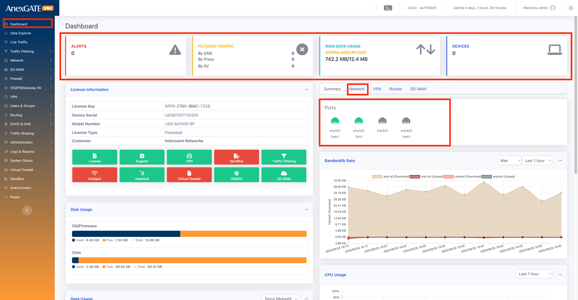
¶ 2. Main Dashboard Tabs
You can toggle between these tabs:
Summary: General system overview.
Network: Shows interface and routing information.
VPN: Status of configured VPN connections.
Routes / SD-WAN: Advanced routing and SD-WAN info.
¶ 3. Ports (Network Tab)
Shows all physical and logical interfaces with their roles:
enp1s0, enp4s0 – WAN interfaces
enp2s0 – LAN interface
enp3s0 – other interfaces
Provides a visual mapping of port roles for quick reference.
¶ 4. License Information
Displays license details such as:
License Key: AJSJ-JSJL-5S45-46UJ
Device Serial Number :AG500-AJ1015
Model Number: AG500P6
License Type (Perpetual / demo )
Customer Name
Also shows quick-action buttons and there subscription
License, Support, VPN, HotSpot, AnexHub, Virtual Firewall, IDS/IPS, SD-WAN, Sandbox, Traffic Filtering
¶ 5. System Resource Usage
Keeps track of device resource utilization:
Disk Usage: Shows storage used by OS/Firmware and Data.
Bandwidth Rate: Live graph of upload/download data rate per interface.
CPU Usage: Graph of CPU consumption over time.
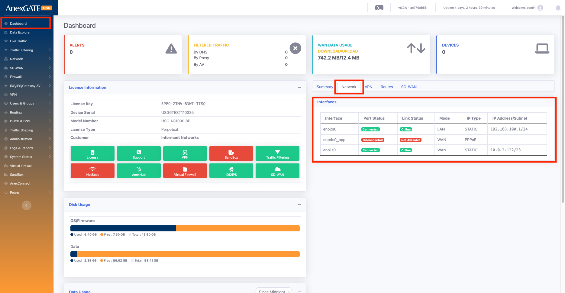
The Network tab provides a clear, real-time view of each interface’s connection status, tracking health, role (LAN/WAN), IP type, and assigned IP details, making it easy to monitor and troubleshoot network connectivity.
Key Information Shown:
Port Status:
Shows whether the link is connected or disconnected (physical link status).
Useful for identifying if the cable or interface is active.
Link Status with Track IP:
- If you configure a Track IP for an interface, the firewall continuously pings that IP to check connectivity.
If ping succeeds → shows Online.
If ping fails → shows Offline.
- If no Track IP is given, the interface’s gateway IP is used as the default Track IP for ping tests.
- In setups with multiple WAN links, the Multi-WAN Track IP is considered as the main reference for link health.
The firewall prioritizes this Multi-WAN Track IP, regardless of any Track IP set on individual interfaces.
If the Multi-WAN Track IP is reachable → interface is Online.
If unreachable → interface is Offline.
Mode:
Indicates whether the interface is configured as LAN or WAN.
IP Type:
Displays whether the interface is using Static IP, DHCP, or PPPoE configuration.
IP Address:
Shows the assigned IP details of each interface.
Helps you quickly verify configured IPs for LAN/WAN.
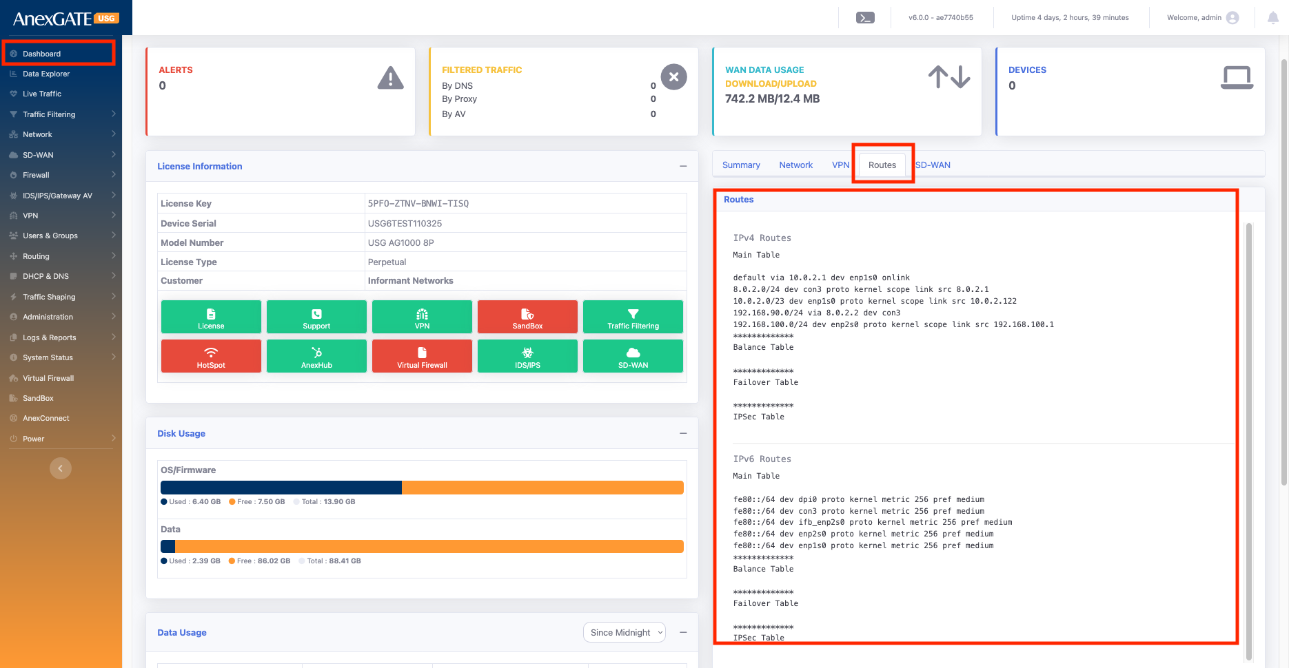
¶ 7. VPN & Routes
Displays configured VPN tunnels, connected clients, and last connection time.
Shows active routing table and any SD-WAN configurations.
¶ Network
¶ WAN/LAN
Network Tab Configuration
In the Network tab, you can configure both LAN and WAN settings with all required details. This section allows you to set IP addresses, gateways, DNS, and other parameters required for proper router connectivity.
LAN Configuration: You can assign the LAN as Static IP and also configure VLANs if needed.
WAN Configuration: WAN can be assigned as Static IP, DHCP, or PPP Dial-up. VLAN settings can also be applied to the WAN interface.
| Element | Sub Element | Description |
Address Type |
Options: IPv4 or IPv6 Select depending on the network requirement. |
|
Provider Name |
Set the name of the ISP provider. Helps identify which provider is linked to the configured interface. |
|
Status |
Enable → Adds the configuration related to the firewall. Disable → Removes all configuration related to this interface. |
|
Name of the Interface |
select interface according to your requirement for example enp1s0, enp2s0 any one you can select | |
VLAN |
You can assign a VLAN ID for LAN / WAN interfaces. Valid range: 1 – 4094 |
|
Interface Type* |
LAN/WAN |
Options: LAN or WAN We an create either LAN or WAN at ones according to your requirement |
Zones |
Assign the interface to a zone: WAN Zone → Select "WAN" LAN Zone → Select "LAN" Custom Zone → Create new zones as needed and apply policies accordingly. |
|
Interface IP Type* |
Static IP/DHCP/PPPOE |
LAN → Only Static option available. WAN → Can use: Static (manually assign IP, mask, gateway, DNS) DHCP (IP assigned automatically by ISP) PPPoE (use ISP-provided username & password) |
Metric |
Used in networking to set route priority; lower values are preferred over higher ones. | |
MTU |
Defines the largest packet size that can be transmitted on the network. | |
IP Address |
ssign the IP address as per requirement: LAN → Internal network IP (e.g., WAN (Static) → Fixed IP provided by ISP WAN (PPPoE) → ISP username & password required |
|
Subnet Mask |
Needed for Static IP configuration. Not required for DHCP or PPPoE. |
|
Description |
Add an interface description for easy identification. (e.g., Office LAN, ISP1 WAN). |
|
Monitor WAN |
Tracking IP is used to ping a specific IP address to monitor connectivity. The interface status will be shown on the dashboard based on the reachability of the tracking IP: If the tracking IP is reachable → status shows Online. If the tracking IP is not reachable → status shows Offline. |
Go to Network > WAN/LAN

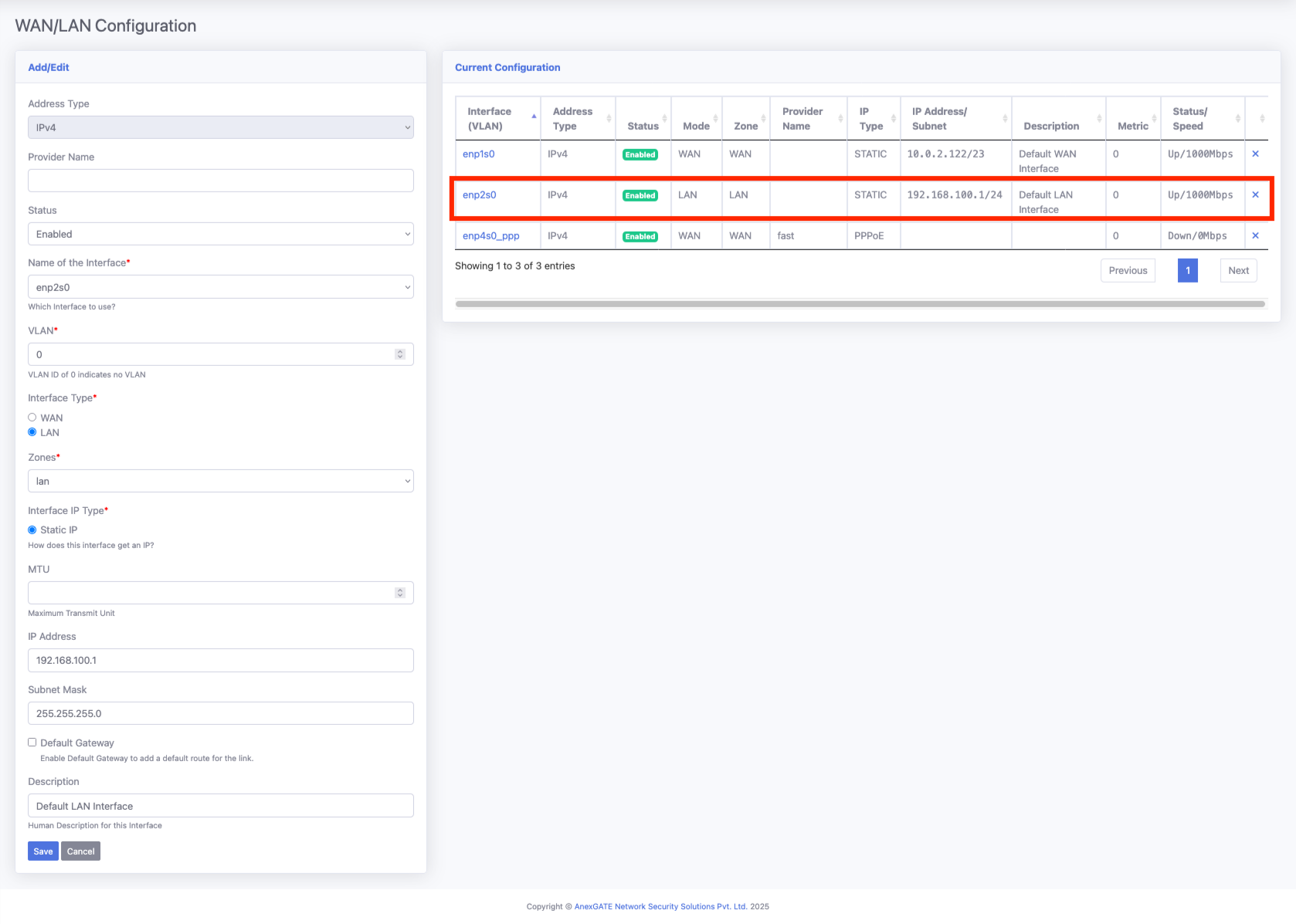
¶ LAN configuration
Below, we configured enp2s0, which is one of the physical ports of the device, as a LAN network. We selected Static IP mode and assigned an IP range with the proper subnet.
Make sure not to select the “Default Route” option here, as it should be used only for the WAN interface.
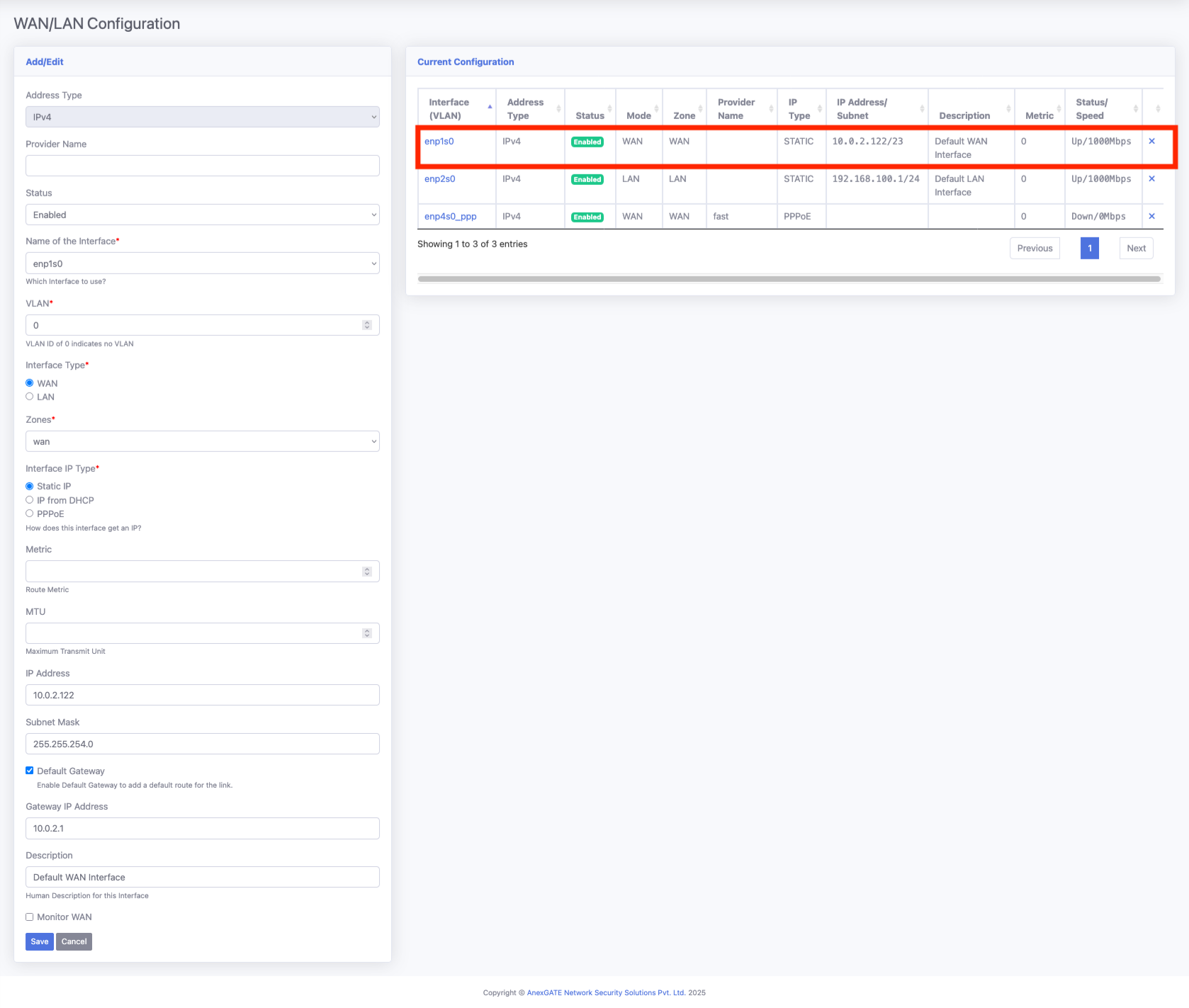
¶ WAN configuration
We selected enp1s0 as the WAN interface in Static mode and configured all required details as shown below. Make sure to select the “Default Route” option — this will add the default gateway for this interface, and all firewall traffic will pass through this default route.
Tracking IP is used to ping a specific IP address to monitor connectivity. The interface status will be shown on the dashboard based on the reachability of the tracking IP:
If the tracking IP is reachable → status shows Online.
If the tracking IP is not reachable → status shows Offline.
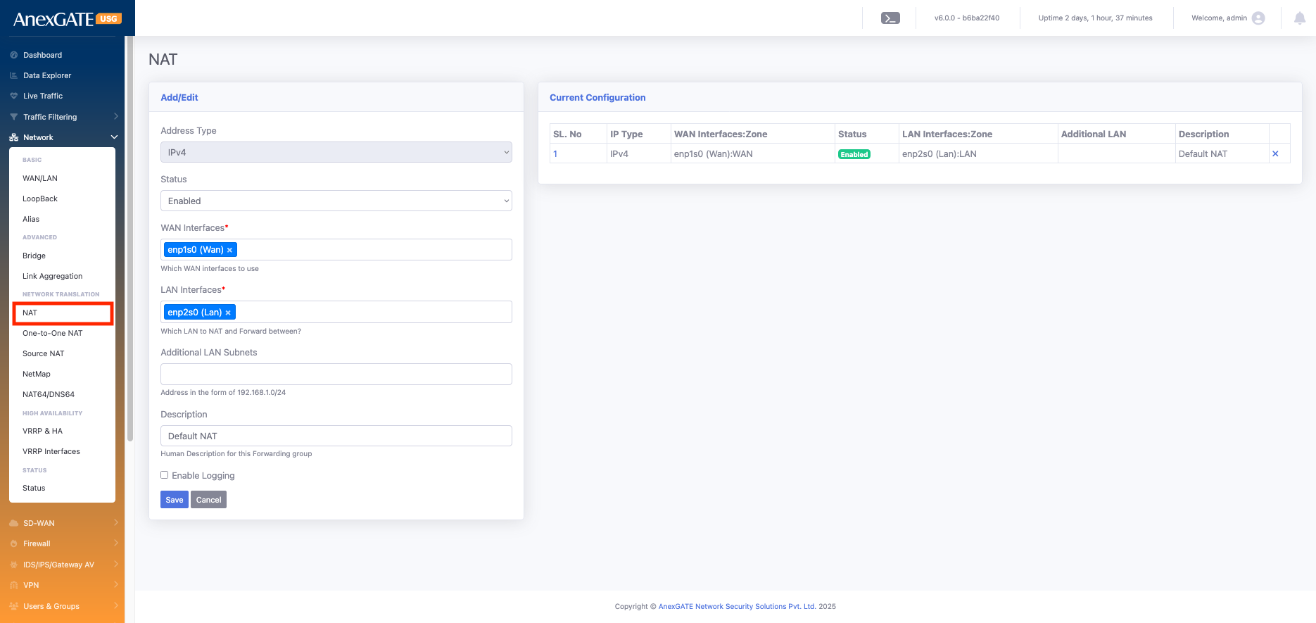
¶ NAT
NAT (Network Address Translation) – Translates private IP addresses to public IP addresses (and vice versa) so internal devices can access external networks (like the internet) and helps conserve public IP
| Element | Description |
Address Type |
Select either IPv4 or IPv6 according to your network requirement. |
Status |
Indicates whether the configuration is Enabled or Disabled. |
WAN Interfaces* |
Select the desired WAN interface(s). You can choose a single interface or multiple interfaces (e.g., enp1s0). |
LAN Interfaces* |
Select the desired LAN interface(s). You can choose a single interface or multiple interfaces (e.g., enp2s0). |
Additional LAN Subnets |
Specifies extra internal subnets (apart from the primary LAN) whose traffic passes through the firewall and requires NAT to reach external networks Example: If VPN users connect with a different subnet than the LAN, you add that subnet here so their traffic is also NATed. |
Description |
Add an interface description for easy identification. |
Go to Network > NAT
¶ Users & Groups
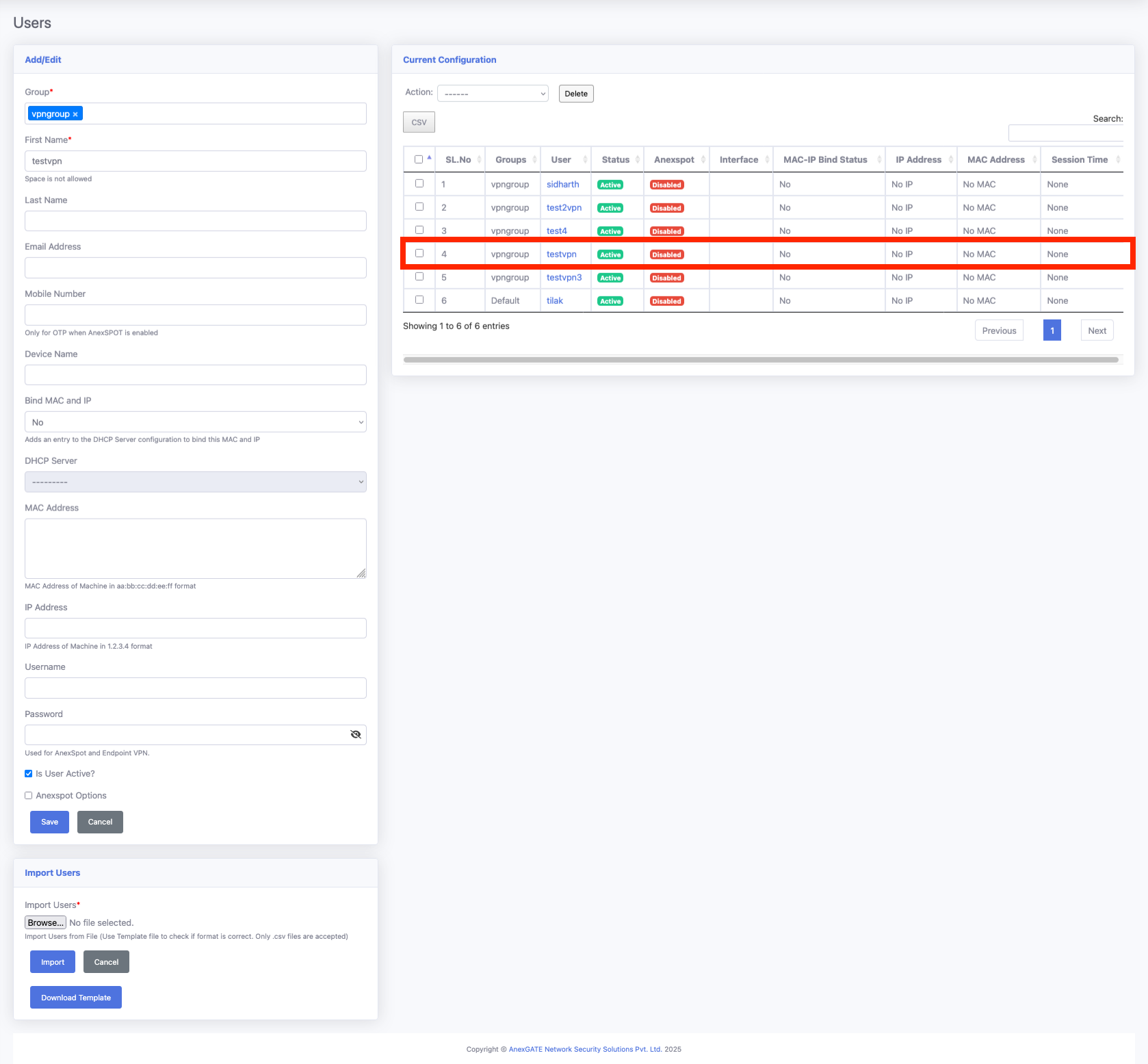
¶ Users
In the User tab, you can create and manage users. These users can be referenced when creating:
Network users
VPN users
ANEXPort login users
You can also bind AMC and DIP with users to generate user-wise reports.
When generating reports and viewing logs, these users can be referenced to track activities and usage.
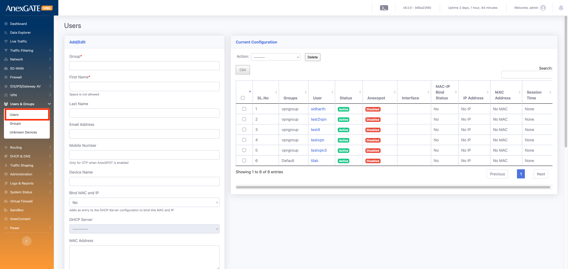
| Element | Description |
| Group* | Select the user group. By default, the Default Group is used. If you have created groups (e.g., ANEXspot, Group, VPN Group), you can select the appropriate one. |
| First Name* | Mandatory field. Provide a short name for easy identification. |
| Last Name | Optional field. Helps in clearer identification; appears in reports for better user recognition. |
| Email Address | Required when using ANEXspot authentication. |
| Mobile Number | Required when using ANEXspot authentication. |
| Device Name | Specify the device name associated with the user. |
| Bind MAC and IP | Allows binding a user to a specific MAC address and IP address for security and tracking. If you select Yes, it binds the MAC and IP; otherwise, keep it as No. |
| DHCP Server | If enabled, assigns an IP address to the user automatically from the selected DHCP server |
| MAC Address | Enter the device’s MAC address if you want to bind it to the user. |
| IP Address | Enter a fixed IP address if you want to assign a static IP to the user. it will MAC binded fro above mac |
| Username | Define the login username for the user. This is used for ANEXspot login. |
| Password | Define the login password for the user. This is used for ANEXspot login. |
| Is User Active? | Enable or disable the user account. You can use this to enable or disable ANEXPort login for the user. |
| Anexspot Options | Additional options available for users when integrated with ANEXPort authentication. |
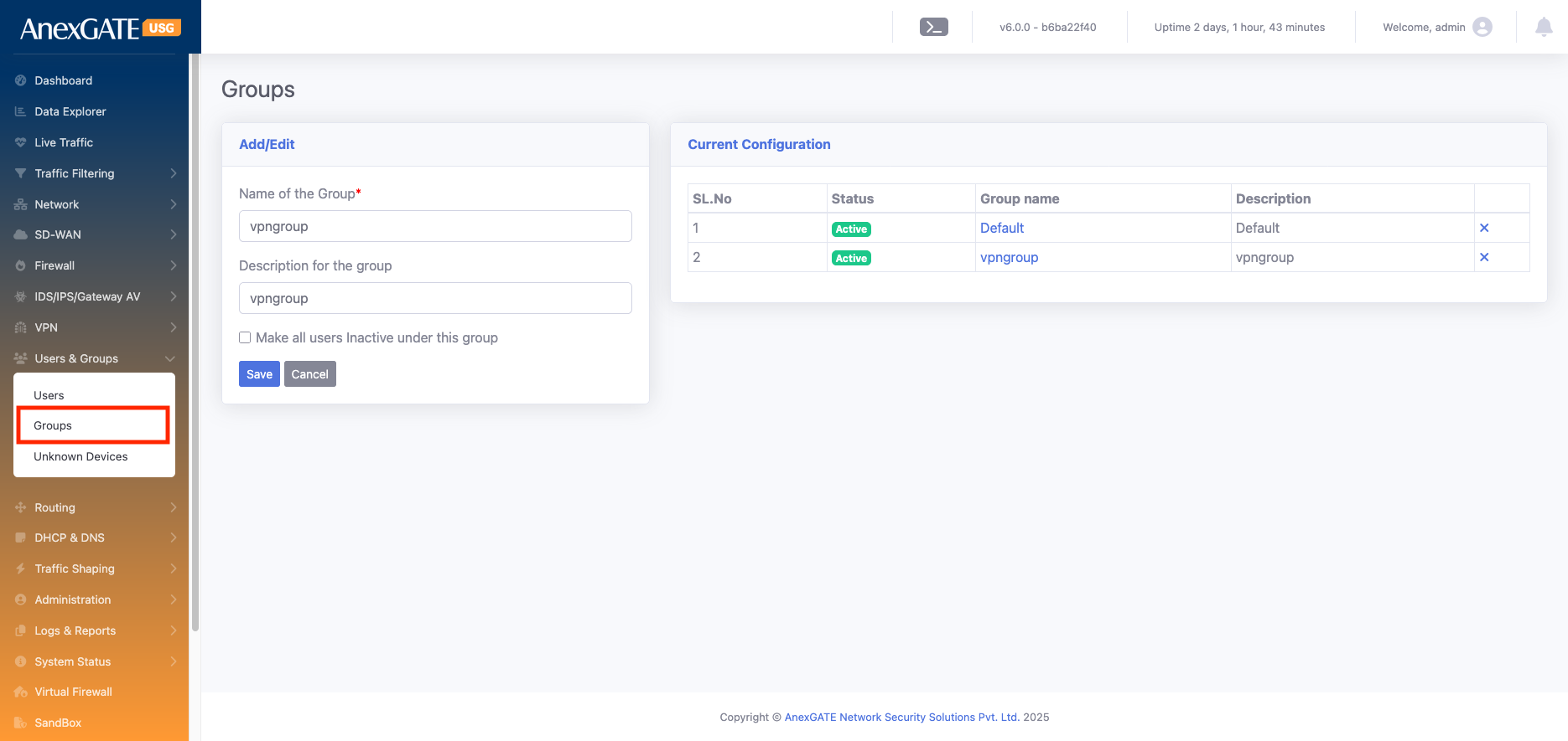
¶ Group
Groups are used to organize users with similar roles or access requirements. By assigning users to a group, you can easily manage permissions, apply policies, and generate reports for all members of that group at once. It also allows bulk actions, like activating or deactivating multiple users simultaneously.
| Element | Description |
| Name of the Group* | Enter a unique name for the group (e.g., VPN Group, ANEXPort Group, etc.). This name will be used to assign users to this group |
| Description for the Group | Provide a short description of the group’s purpose (e.g., “Users for VPN access” or “Guest network users”). |
| Make all users Inactive under this group | Enables you to deactivate all users associated with this group at once, without removing them. This is useful for temporarily disabling access for all group members. |
Go to User & Group > Group >
¶ VPN
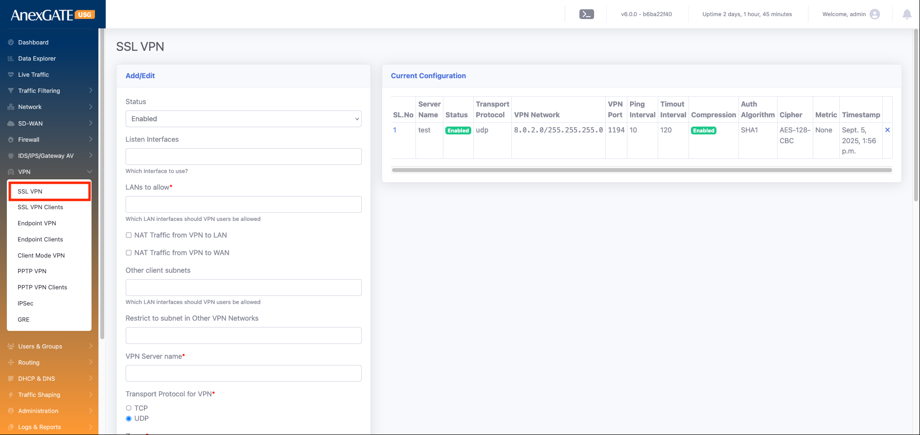
SSL VPN (Secure Sockets Layer Virtual Private Network) is used to provide secure remote access to a private network over the internet. It encrypts traffic between the user’s device and the network, allowing users to safely access internal resources, applications, and data from anywhere without requiring a dedicated VPN client.
We can use the VPN server as a gateway for the network. It can also be part of the network, allowing devices to connect through it and securely access network resources.
¶ SSL VPN
SSL VPN can be used to establish secure communication between two devices over the internet. In this setup:
Server Configuration:
One device is configured as the SSL VPN server with a public IP address.
The server can support failover between multiple public IPs if required, eliminating the need for multiple VPN servers or separate tunnels.
Client Configuration:
Multiple clients can connect to the server using individual certificates. Each client receives a unique certificate during creation.
Client devices do not require a public IP address; the tunnel is established from the client to the server securely over the internet.
Network Communication:
For example, if there is 1 Head Office (HO) and 5 branch offices:
The HO has a static public IP, and branches may not have public IPs.
An SSL VPN tunnel can be established between the HO LAN and each branch LAN, allowing communication between HO and branches.
Branch-to-branch communication is also possible through the HO tunnel, enabling a full-mesh secure network using a single VPN server.
Advantages:
`No need for public IPs on branch devices.
Each client has a unique certificate for enhanced security.
Centralized VPN server simplifies management and supports failover handling.
Enables secure LAN-to-LAN and branch-to-branch communication.
Dynamic route distribution: Any new subnet created at the HO (or reachable through HO) can be made available to all branches by simply adding the route at the server; no manual configuration is required at each branch
| Element | Description |
| Status |
Defines whether the VPN service is enabled or disabled. If disabled, no clients can connect, and no routes will be pushed. |
| Listen Interfaces |
The physical or virtual network interface on which the VPN server listens for incoming connections. Example: |
| LANs to allow* |
Select the LAN interfaces that remote VPN clients should be able to access. Example: If you want VPN users to reach the internal office LAN, you must select that LAN interface here. |
| NAT Traffic from VPN to LAN |
If enabled, traffic coming from VPN clients will be NATed (masqueraded) when reaching the LAN. Useful when LAN devices don’t have routes to VPN subnets |
| NAT Traffic from VPN to WAN |
NATs VPN client traffic when it goes out through the WAN interface (e.g., to the internet). Ensures VPN clients can browse the internet securely through the firewall |
| Other client subnets |
If a VPN client itself has a subnet (e.g., branch office network behind the client), that subnet will automatically be added here. No need for manual addition — it is learned from the client configuration. |
| Restrict to subnet in Other VPN Networks |
Used when you have multiple VPNs (local LAN, remote LANs, client WANs). Adds specific routes that must be pushed to every client to restrict or allow communication across those VPN networks. Ensures controlled routing between connected networks. |
| VPN Server name* |
The identifier of the VPN server. Useful for administration and troubleshooting. |
| Transport Protocol for VPN* |
Defines how VPN packets are transported: UDP (faster, preferred for VPN traffic) TCP (more reliable, but slightly slower) |
| Zones | |
| Cipher |
The encryption algorithm used to secure VPN traffic. Examples: AES-256, AES-128. Stronger cipher = more secure, but can affect performance. |
| Auth Alogrithm |
Algorithm for data integrity verification. Common options: SHA-256, SHA-512. Ensures packets are not tampered with in transit. |
| VPN Network IP space* |
The IP range (subnet) assigned to VPN clients. Example: Every client receives an IP from this pool. |
| VPN Network Subnet Mask* |
Defines the size of the VPN client network. Example: |
| Port for VPN service* |
The port number where the VPN service listens for incoming connections. Common default: Can be customized if needed for security. |
| Client Primary DNS |
DNS server pushed to clients when they connect. Example: |
| Client Secondary DNS |
ckup DNS server in case the primary is unreachable. Example: |
| Keepalive Ping* |
Used to maintain the connection and detect dead peers. The server pings the client periodically; if no response, it resets the tunnel. Ensures reliability. |
| Enable Compression |
Option to compress VPN traffic before encryption. Can improve performance on slow links, |
| Route Metric |
Sets the priority of VPN routes compared to other routes. Lower value = higher priority. Useful when multiple VPNs or WAN paths exist. |
¶ SSL VPN client
hrough the SSL VPN configuration, you can create multiple clients for secure remote access. Each client is uniquely identified and authenticated to establish a tunnel with the VPN server.
| Element | Description |
| Status | Enables or disables the specific client profile. Set it to Enable to activate the client for connection |
| VPN Server* | Select the VPN server that this client will connect to. This defines which server endpoint the tunnel will be established with |
| User | Choose the user account associated with this client. This links the VPN connection to a specific user for authentication, reporting, and access control |
| Tunnel IP | Assign a unique IP address for the client inside the VPN tunnel (e.g., 10.8.0.2). Each client must have its own unique tunnel IP to avoid conflicts. |
| Client LAN Subnets | Define the LAN subnets behind the client device (e.g., 192.168.10.0/24). This tells the VPN server which networks at the client side should be reachable through the tunnel. |
| Client Float Route | When enabled, the VPN server will automatically add a route to the client’s LAN subnet whenever the tunnel is up. If the tunnel goes down, the server automatically removes that route. This keeps the server’s routing table clean and avoids stale routes. |
| Local Route | When enabled, it adds a route in the VPN server’s routing table for the client’s LAN subnet. This allows devices in the VPN server’s LAN to reach the client’s LAN network through the tunnel. |
| Broadcast Client Subnet | Controls whether the client’s LAN subnet is pushed to all other VPN clients. When enabled, the server advertises this client’s LAN network to every other connected client so that client-to-client communication is possible through the VPN tunnel. |
| Passphrase | An extra layer of security that encrypts the client’s key/certificate file. The client needs to enter this passphrase during connection for added protection. |
| Full Tunnel Mode | If enabled, all client traffic (internet + private) is routed through the VPN tunnel for maximum security. If disabled, only traffic destined for internal subnets defined in routes is sent through the tunnel (split-tunnel mode). |
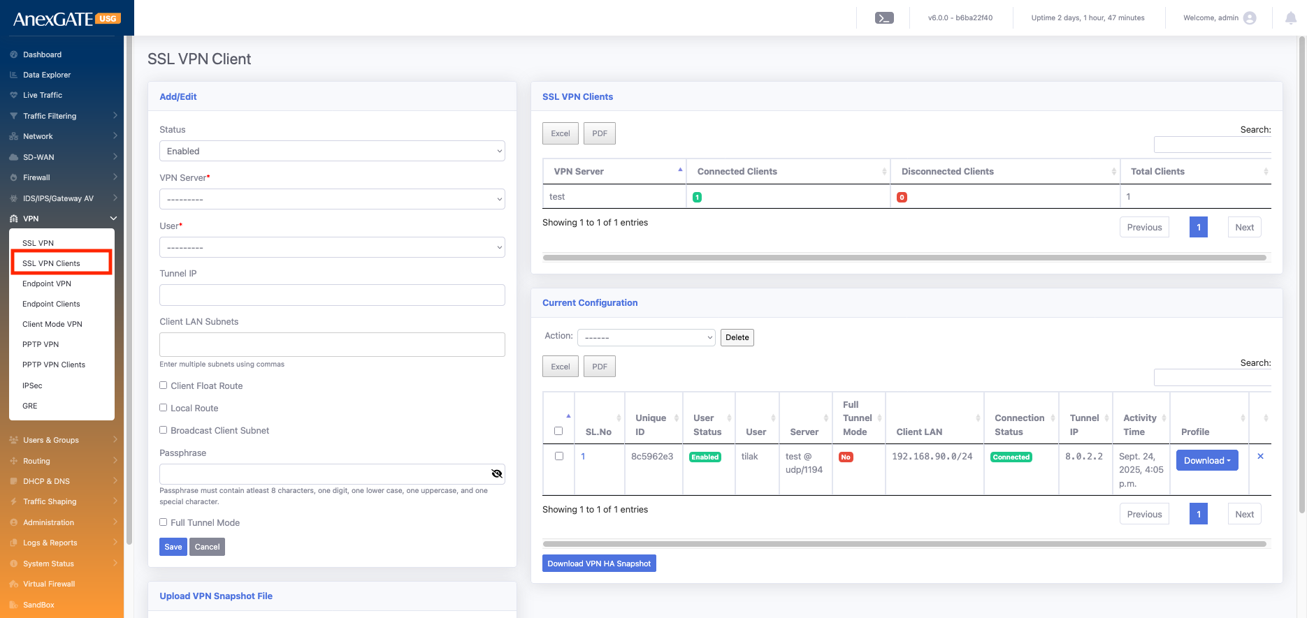
In this section, you can see all the configured SSL VPN client details along with their connection status (Connected or Disconnected), the last status update time, and statistics showing how many clients have been created, how many are currently connected, and how many are disconnected.
¶ System Status
¶ Command
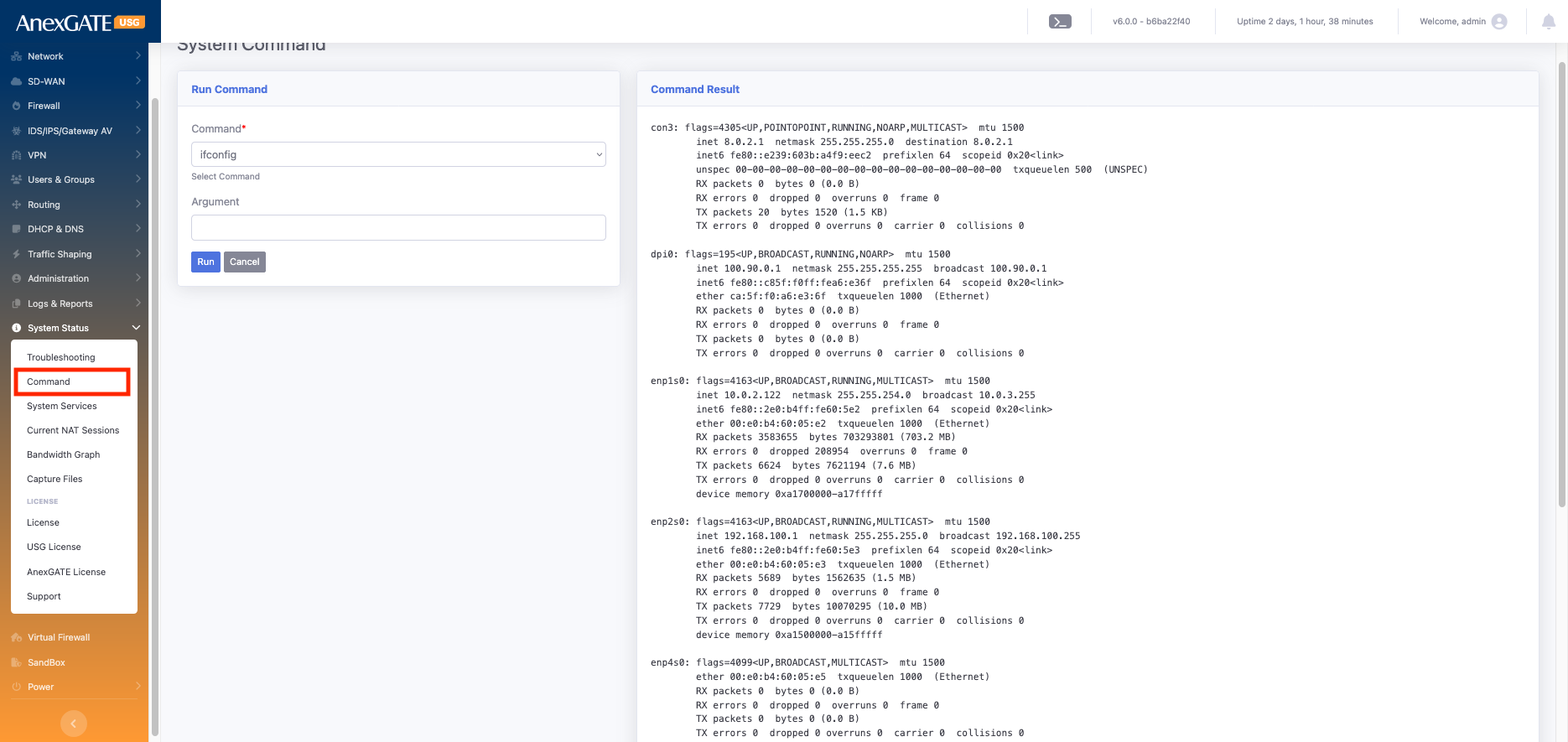
Go to Command > select ifconfig > run
The ifconfig (interface configuration) command in Linux is used to view and configure network interfaces.
When you run ifconfig, it displays all active interfaces such as LAN, WAN, VPN, and loopback, along with their details like:
IP address, Subnet mask, and Broadcast address
MAC address (Hardware address)
Interface status (UP, DOWN, RUNNING)
RX (Received) and TX (Transmitted) bytes and packets, showing the data flow through the interface
This command is very useful for troubleshooting and checking the live status of all network interfaces on the device.
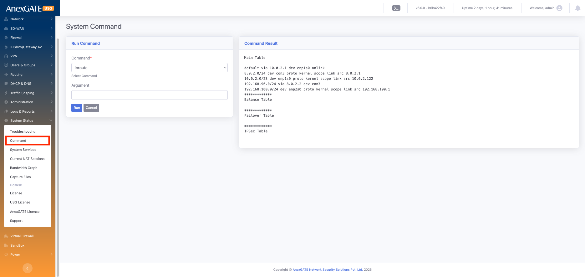
Go to Command > select : iproute > run
The ip route command in Linux is used to display and manage the routing table of the system or firewall.
When you run iproute it lists all the network routes that the firewall uses to forward traffic.
- It shows details such as:
Destination networks and their subnets
Gateway IP addresses used to reach those networks
Interface names (e.g., enp1s0, enp2s0) through which the traffic exits
Default route, which is used for all traffic not matching any other specific route
Metric values, which decide priority if multiple routes exist for the same network
This command is crucial for verifying whether the firewall is correctly routing traffic to internal networks, VPN tunnels, or the internet.
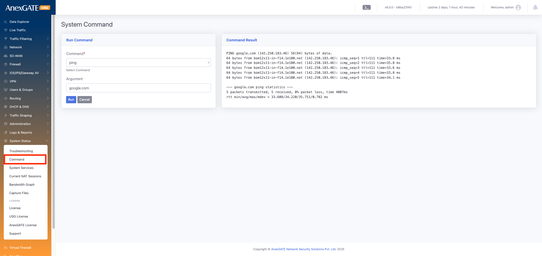
Go to Command > select : ping > argument : google.com > run
The ping command is used to test connectivity between your system and another network device (like a server, router, or IP address). It works by sending ICMP Echo Request packets to the target and waiting for Echo Reply packets.
- When you run
ping, it shows:
Whether the target is reachable (online) or not (offline)
Response time for each packet (latency)
Packet loss, if any, indicating network issues
- Use cases:
Verify if a host or gateway is reachable
Check network latency and performance
Troubleshoot network issues