¶ GETTING STARTED
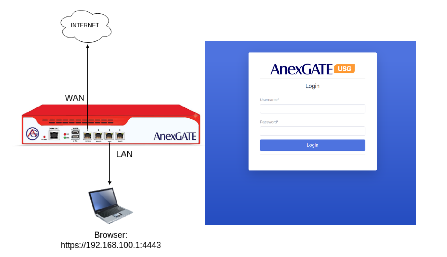
Connect the standard issued Power Adapter/Chord which comes packed with the AnexGATE USG AG200 Plus Pro Firewall.
Connect the Laptop or PC to LAN Port mentioned on the USG Firewall.
Configure the Laptop to be in DHCP mode to get the IP Address from the USG Firewall DHCP server automatically.
By default, 192.168.100.1 is configured as LAN Gateway in the USG Firewall.
Open the browser in PC, put the URL https://192.168.100.1:4443 in order to access the Firewall Dashboard on the Local LAN PC connected to USG Firewall.
By default, the USG Firewall Login credentials are as follows:
Username: admin
Password: admin@123#
NOTE:
Do not remove or tamper with the sticker applied on the USG. Tampering with the AnexGATE USG Warranty Sticker will void warranty.
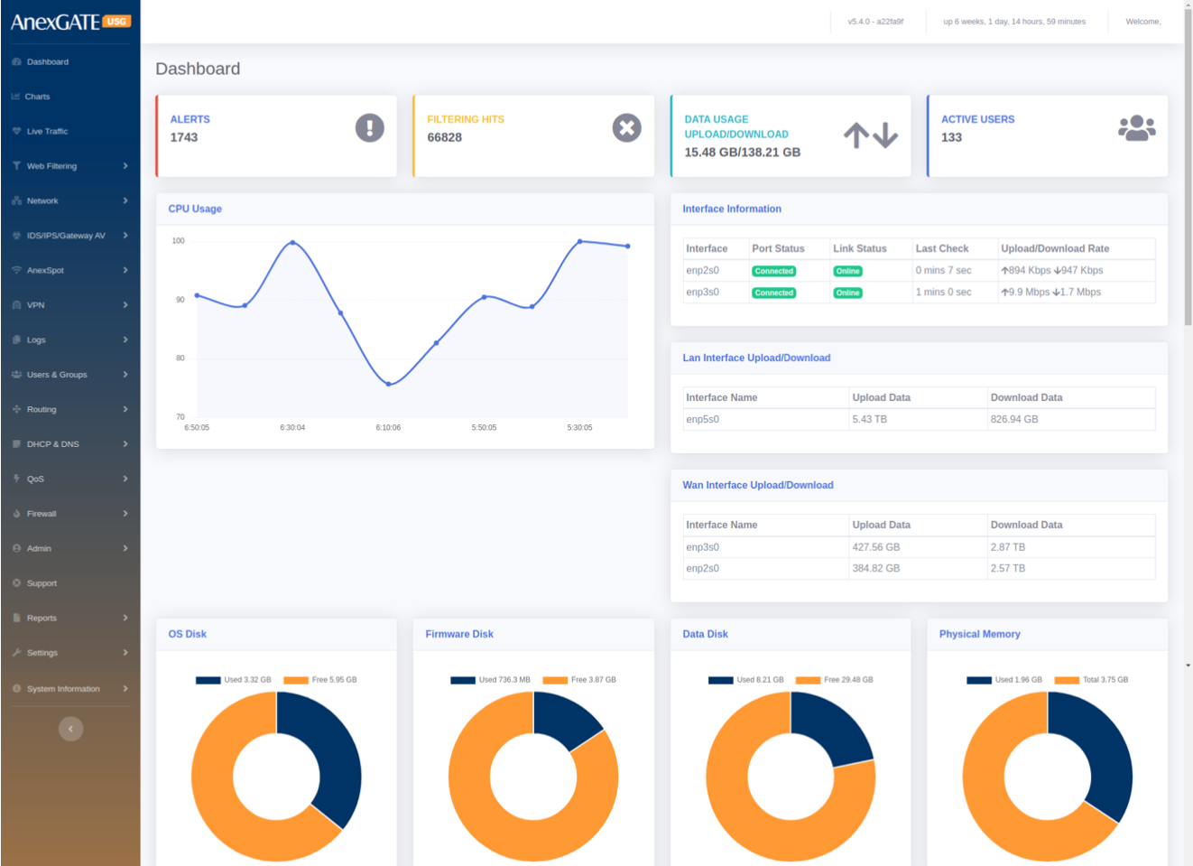
¶ 1. DASHBOARD
The Dashboard shows general AnexGATE USG Firewall information and provides a quick overview of all the important parameters of your appliance that requires attention such as the software version, status of each interface, resource utilization, IPS alerts and so on which are mentioned as follows:
¶ PARAMETERS
| ELEMENTS | DESCRIPTION |
|---|---|
| Alerts | Displays the IDS / IPS Inbound and Outbound malicious traffic hits. |
| Filtering Hits | Displays Blocked sites which are configured under Web-Filtering policy. |
| Data Usage | Displays Upload and Download Data Traffic usage . |
| Users | Displays the number of connected Users. |
| CPU Usage | Shows the usage of CPU in a graphical representation. |
| Interface Information | Displays WAN Status along with Upload/Download rate. Link status is check runs every one minute. |
| LAN/WAN Interface Upload/Download rate | Displays Inbound and Outbound Traffic statistics on the LAN/WAN interface. |
| OS Disk | Displays used/available OS partition partition Usage. |
| Firmware Disk | Displays used/available Firmware Disk partition Usage. |
| Data Disk | Displays used/available Data Disk partition Usage. |
| Physical Memory | Displays used/available RAM memory. |
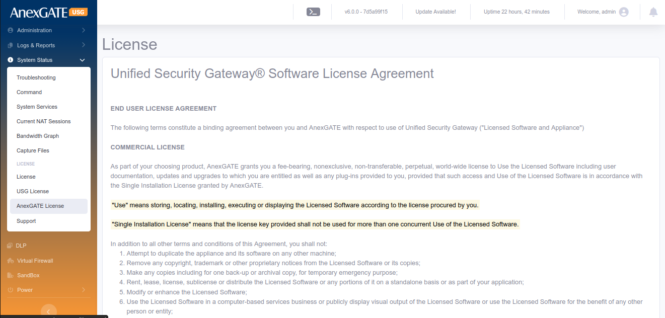
| License Information | Displays License Information of the customer. Click on License Details to check the license information in detail. |
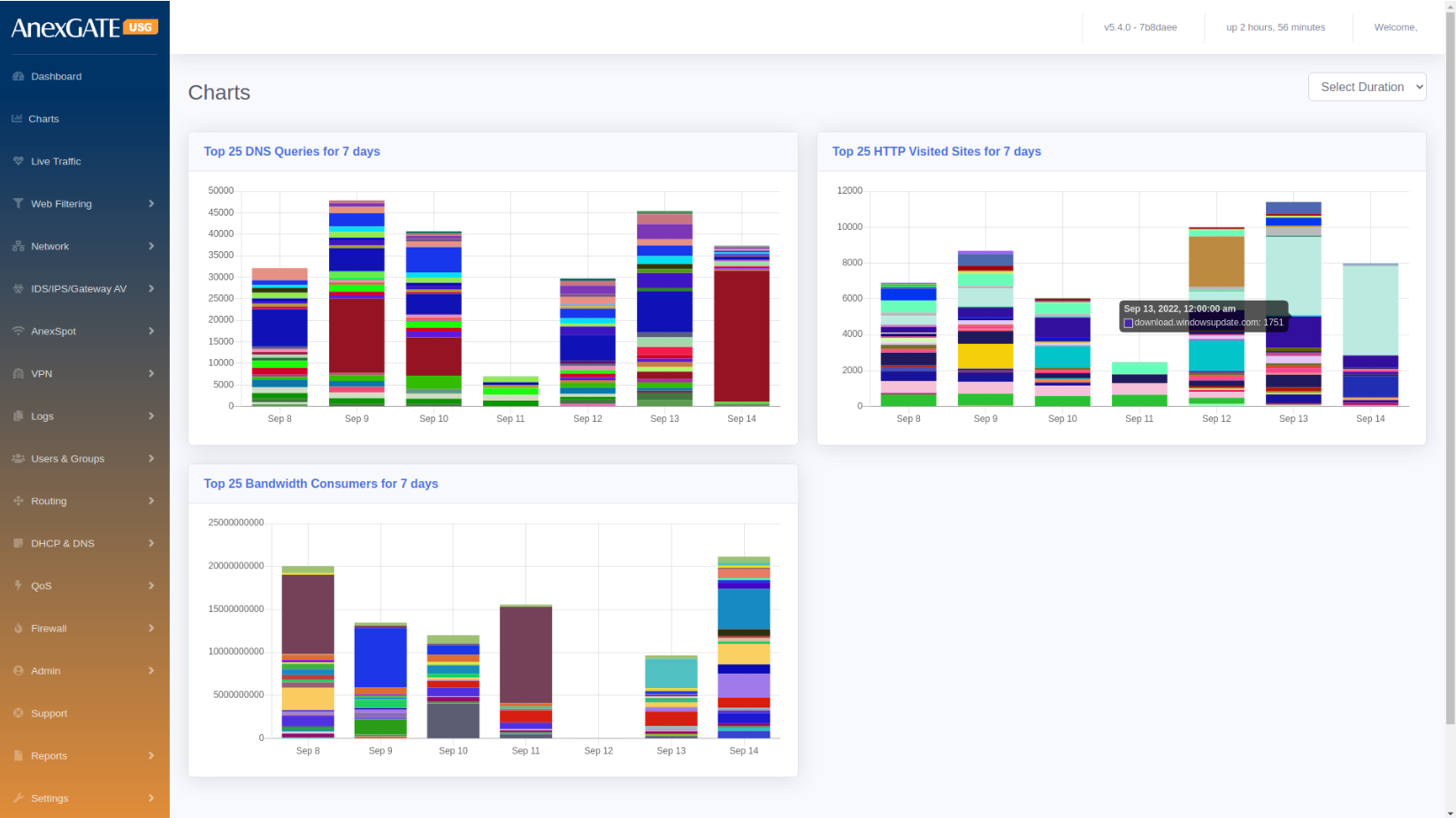
¶ 2. CHARTS
Charts displays the visual representation of the below parameters. Hovering the mouse on colored graph will highlight the statistics recorded.
¶ PARAMETERS
| ELEMENTS | DESCRIPTION |
|---|---|
| DNS Queries | Displays Top 25 DNS Queries for 7 days. |
| HTTP Visited Sites | Displays Top 25 HTTP Visited Sites for 7 days. |
| Bandwidth Consumers | Displays Top 25 Bandwidth Consumers for 7 days. |
NOTE: Charts upto 4 weeks can be viewed by selecting the duration on top-right corner of the Charts.
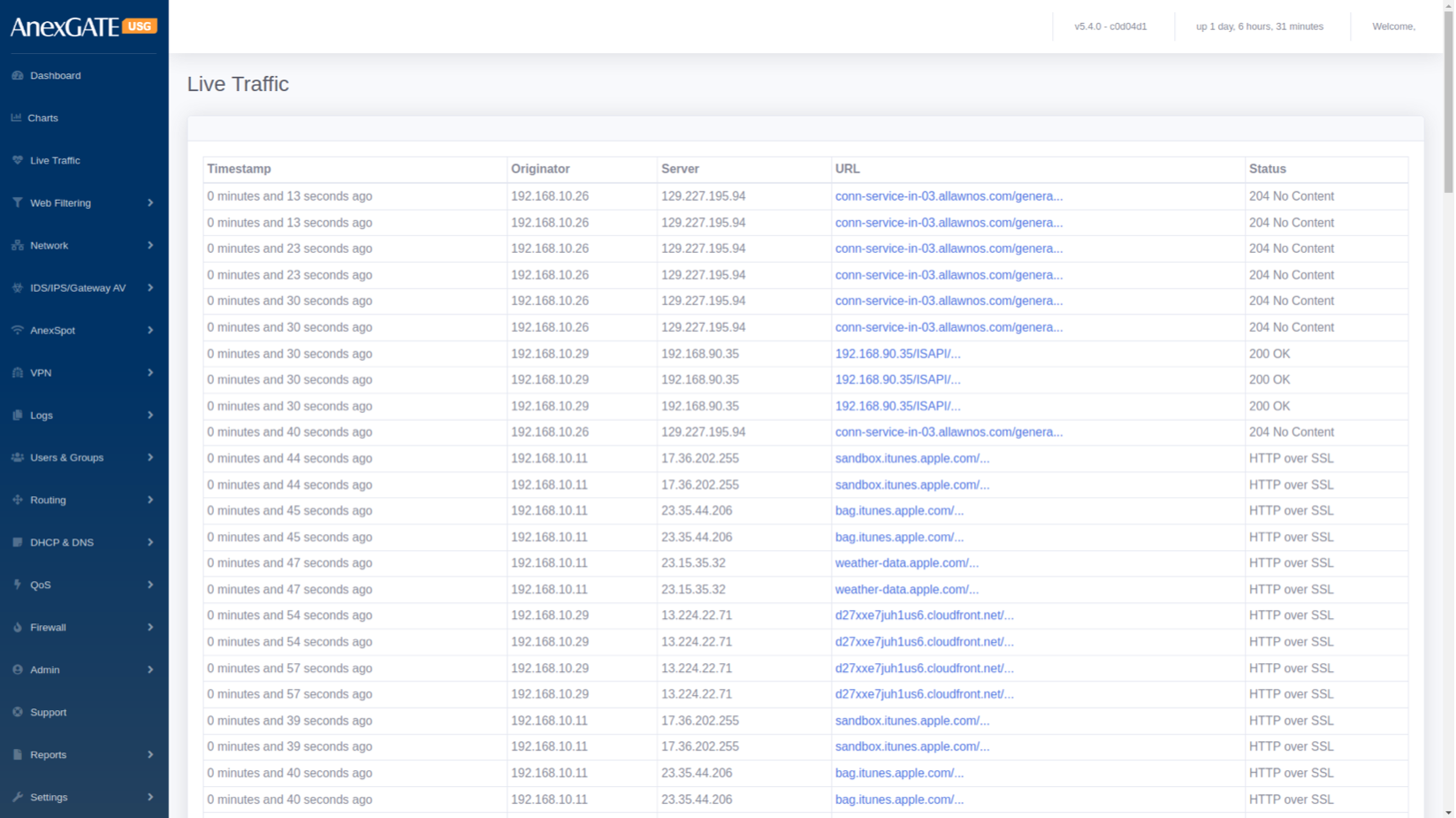
¶ 3. LIVE TRAFFIC
The Live Traffic displays the traffic through a firewall in a table format. The Live Traffic Report of a firewall are automatically updated to show details of incoming and outgoing traffic for each monitored firewall.
| ELEMENTS | DESCRIPTION |
|---|---|
| Timestamp | Displays Date & Time in hh:mm:ss, of the Inbound & Outbound data traffic. |
| Originator | Displays LAN IP address for Inbound or Outbound data traffic. |
| Server | Displays Destination IP Address Inbound or Outbound data traffic. |
| URL | Displays URL of the Inbound or Outbound data traffic. |
| Status | Displays HTTP/s Response Status Code issued by a server in response to a client's request made to the server. |
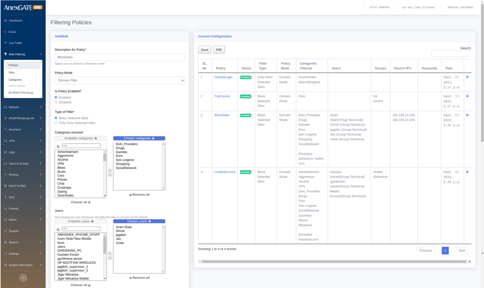
¶ 4. WEB FILTERING
User can allow or block internet content by creating Web Filtering Policies. If no user or group is selected in a policy, it will be considered to apply as a Global policy.
¶ 4.1 POLICIES
To configure Web Filtering, go to Web Filtering > Policies.
¶ PARAMETERS
| ELEMENTS | DESCRIPTION |
|---|---|
| Description for Policy* | Add a description to the Web Filtering Policy. |
| Policy Mode |
Select Domain Mode Filtering or Proxy Mode Filtering. NOTE: Proxy must be enabled under Web Filtering > HTTP/HTTPs Proxy before applying Web Filtering policy as Proxy Mode Filtering. |
| Is Policy Enabled? | Enable or Disable the Web Filtering Policy. |
| Type of Filter |
Block Selected Sites: to block selected sites from list of categories. Only Allow Selected Sites: To allow only select sites from list of categories. |
| Categories Blocked |
List of categories to block or allow. Example: Advertisement, Porn, Social Networking etc.. |
| Users |
Select users on which the policy needs to be applied. Users and Groups must be configured before configuring policies. |
| Groups | Select Group/s on which the filtering policy needs to be applied. |
| Source IPs | Select Source IPs on which the filtering policy needs to be applied. |
| URL | Allow or Block URL of particular site. (Applies for Transparent Interception Mode only.) |
| Exclude Sites | Sites can be excluded from list of categories which are blocked or allowed. Example: Adding facebook.com in exclude where Social Networking category is Blocked will allow facebook.com |
| Keywords |
Keywords to block. Seperate multiple keywords by comma. **Keyword Filtering is only done on HTTP and Domain Name traffic. |
| SAVE | Save the Web Filtering configuration settings. |
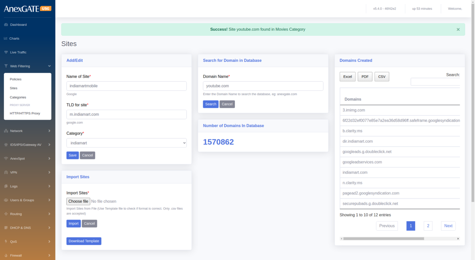
¶ 4.2 SITES
To create custom category sites, Go to Web Filtering > Sites.
¶ PARAMETERS
| ELEMENTS | DESCRIPTION |
|---|---|
| Name of Site* | Enter a name of the website to be added. |
| TLD for Site | Enter a domain (Ex: google.com) name of the website to allow or block. |
| Category | Select the category to which the website domain to be associated with. |
| Search Domain Name* | Enter domain name to check the category of the domain entered. |
| Number of Domains in Database | Displays total number of websites added into categories. |
| Domains Created | Displays manually created site category database. |
| Import Sites | Import multiple sites by downloading an .csv template and uploading to the Import Sites option. |
| SAVE | Save the Site configuration settings |
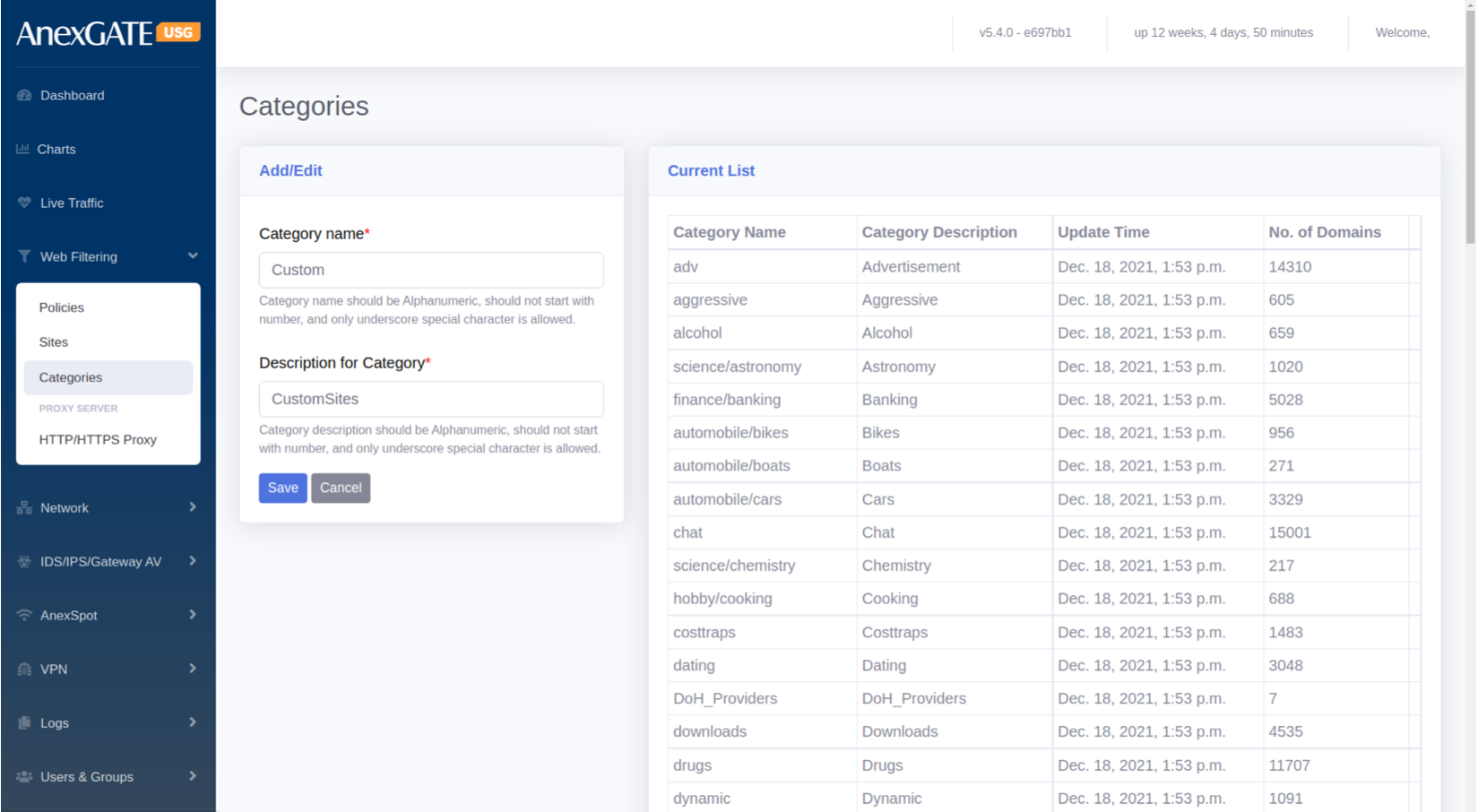
¶ 4.3 CATEGORIES
Categories are the groups for the manual TLD sites to be listed under the Category if they are not listed under Domain Database in Sites. These manual categories can be used in Web Filtering to block or allow sites mentioned manually under new created Category.
¶ PARAMETERS
| ELEMENTS | DESCRIPTION |
|---|---|
| Category Name | Enter the name of Category to be created and listed under Site Category. |
| Description for Category | Add a Description for the Category. |
| SAVE | Save the Category configuration settings. |
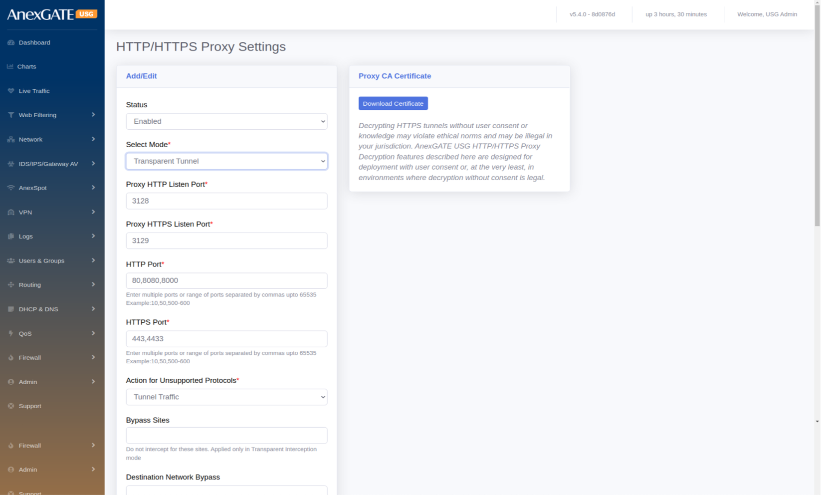
¶ 4.4 HTTP/HTTPS PROXY SETTINGS
To configure Proxy to enable Proxy based Web Filtering, User should select the policy mode to Proxy Mode Filtering. To enable Web Proxy, Go to Web Filtering > HTTP/HTTPs Proxy.
¶ PARAMETERS
| ELEMENTS | DESCRIPTION |
|---|---|
| Status | Enable or Disable the state of Proxy Mode or Proxy Server. |
| Select Mode* |
Explicit – Select this mode to manually configure Proxy in the browser to access Destination Target. Transparent Tunnel – Select this mode to get automatically redirected from the Proxy Server to access Destination Target. Transparent Interception – Select this mode specially for the HTTPS Interception by using CA Certificate to decrypt. NOTE: Proxy CA Certificate needs to be downloaded and imported in each Sytem-PC browser, in order to use Transparent Interception and access the internet. |
| Proxy HTTP Listen Port* | 3128 is the default port number where the HTTP/TCP proxy listens for HTTP traffic. Any client applications that communicate with the proxy must also be set to the same port. |
| Proxy HTTPS Listen Port* | 3129 is the default port number where the HTTP/TCP proxy listens for HTTPS traffic. Any client applications that communicate with the proxy must also be set to the same port. |
| HTTP Port* | 80,8080,8000 are set as defaults for the Destination to be reached. |
| HTTPS Port* | 443,4433 are set as defaults for the Destination to be reached. |
| Action for Unsupported Protocols* |
Tunnel Traffic – Unsupported Protocols are accepted & allowed through the proxy server in the firewall Reject Request – Unsupported Protocols will be rejected if not specified in the Proxy. |
| Bypass Sites |
The mentioned sites will be bypassed without CA certificate. (For Transparent Interception mode only). |
| Destination Network Bypass | Destination IP Address/Networks must be entered to be bypassed without CA certificate (For Transparent Interception mode only). |
| Source MAC Bypass |
The mentioned Destination IP Address / Networks will be bypassed without any interuption by the proxy for the CA certificate. (For Transparent Interception mode only). |
| Source IP Bypass | The mentioned Source IP Address/Networks will be bypassed without CA certificate. (For Transparent Interception mode only). |
| Default Action |
Deny – Configured Proxy state will be in Deny Action mode. Allow – Configured Proxy state will be in Allow Action mode. |
| DNS Redirect to Firewall |
Force the proxy to use USG as a DNS Server. If not selected, DNS forwarders are used for DNS queries by the Proxy Engine. |
| SAVE | Save the HTTP/HTTPs Proxy configuration settings. |
¶ 5. NETWORK
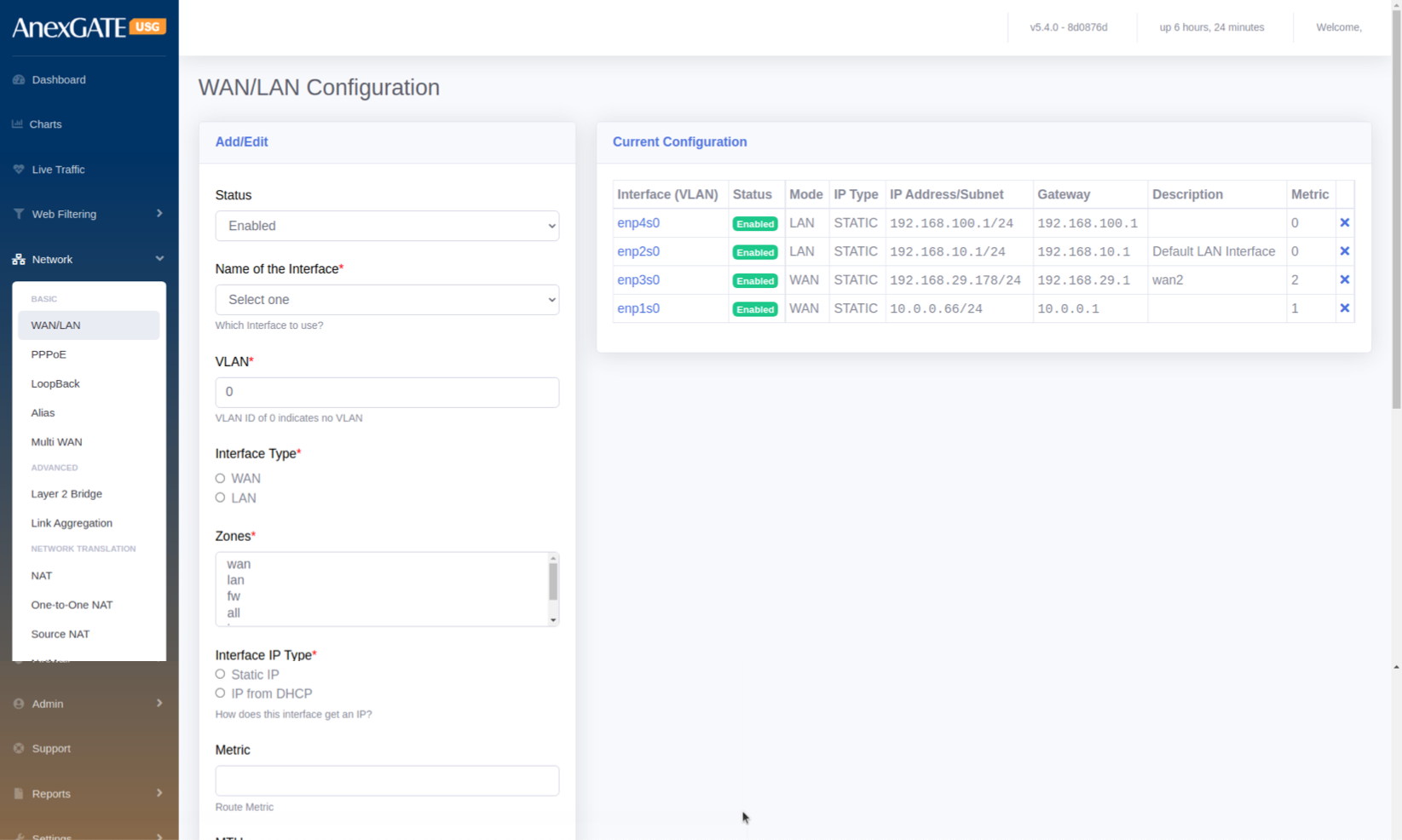
¶ 5.1 WAN/LAN
To configure interfaces as LAN, WAN, DMZ etc..., Go to Network > WAN/LAN.
¶ PARAMETERS
| ELEMENTS | DESCRIPTION |
|---|---|
| Status | Enable or Disable the LAN/WAN Interface. |
| Name of the Interface | Select the Interface from the dropdown list of Interfaces. (Example: enp1s0,enp2s0 etc...) |
| VLAN | Assign a VLAN for LAN Interfaces. By default VLAN ID is set to 0 |
| Interface Type |
WAN – Select this to configure WAN Interface link from ISP LAN – Select this to configure Local Area Network. |
| Zones | Select Zone according to the configuration to be done. |
| Interface IP type |
Static IP – Select Static IP for LAN/WAN. DHCP – Select this for IP to be provided from upstream router’s DHCP server NOTE: LAN must always be configured with Static IP Address. |
| Metric | Add metric if multiple WAN Interfaces are configured. |
| MTU | Assign Maximum Transmission Unit (MTU in bytes) for interface manually or leave it blank for automatic configuration. |
| Track IPs | Enter Track IPs for Link Monitoring of WAN links. |
| IP Address | Enter IP Address to be assigned for Firewall. |
| Subnet | Enter Subnet to be assigned for Firewall. |
| Gateway IP Address | Enter Gateway IP Address to be assigned for Firewall. |
| Description | Add a description to the WAN/LAN Configuration. |
| SAVE | Save the LAN/WAN configuration settings. |
¶ 5.2 PPPoE
To configure PPPoE Dial Up, Go to Network > PPPoE.
¶ PARAMETERS
| ELEMENTS | DESCRIPTION |
|---|---|
| Status | Enable or Disable the LAN/WAN Interface. |
| Name of the Interface* | Select the Interface from the dropdown list of Interfaces. (Example: enp1s0,enp2s0 etc...) |
| VLAN* | Assign a VLAN for LAN Interfaces. By default VLAN ID is set to 0 |
| Zones* | Select WAN to configure PPPoE Link. |
| Name of Provider* | Enter the name of the Internet Service Provider. |
| Service Name | Provide a service name only if your ISP expects a service name during dial up. |
| Username* | Enter the Username provided by the ISP for PPPoE Dial Up. |
| Password* | Enter the Password provided by the ISP for PPPoE Dial Up. |
| Metric | Add metric if multiple WAN Interfaces are configured. |
| Use PPP Routing | Use the PPP connection as the default route. Disable this option if using in failover or aggregation mode. |
| Redial Period | Enter Redial Period if the PPPoE doesnt dial up. By default, Redial Period is 20. |
| IP Address | Enter the Public IP Address if the connection is Static. |
| Track IPs | Enter Track IPs for Link Monitoring of WAN links. |
| Description | Add a description to the PPPoE Configuration. |
| SAVE | Save the PPPoE configuration settings. |

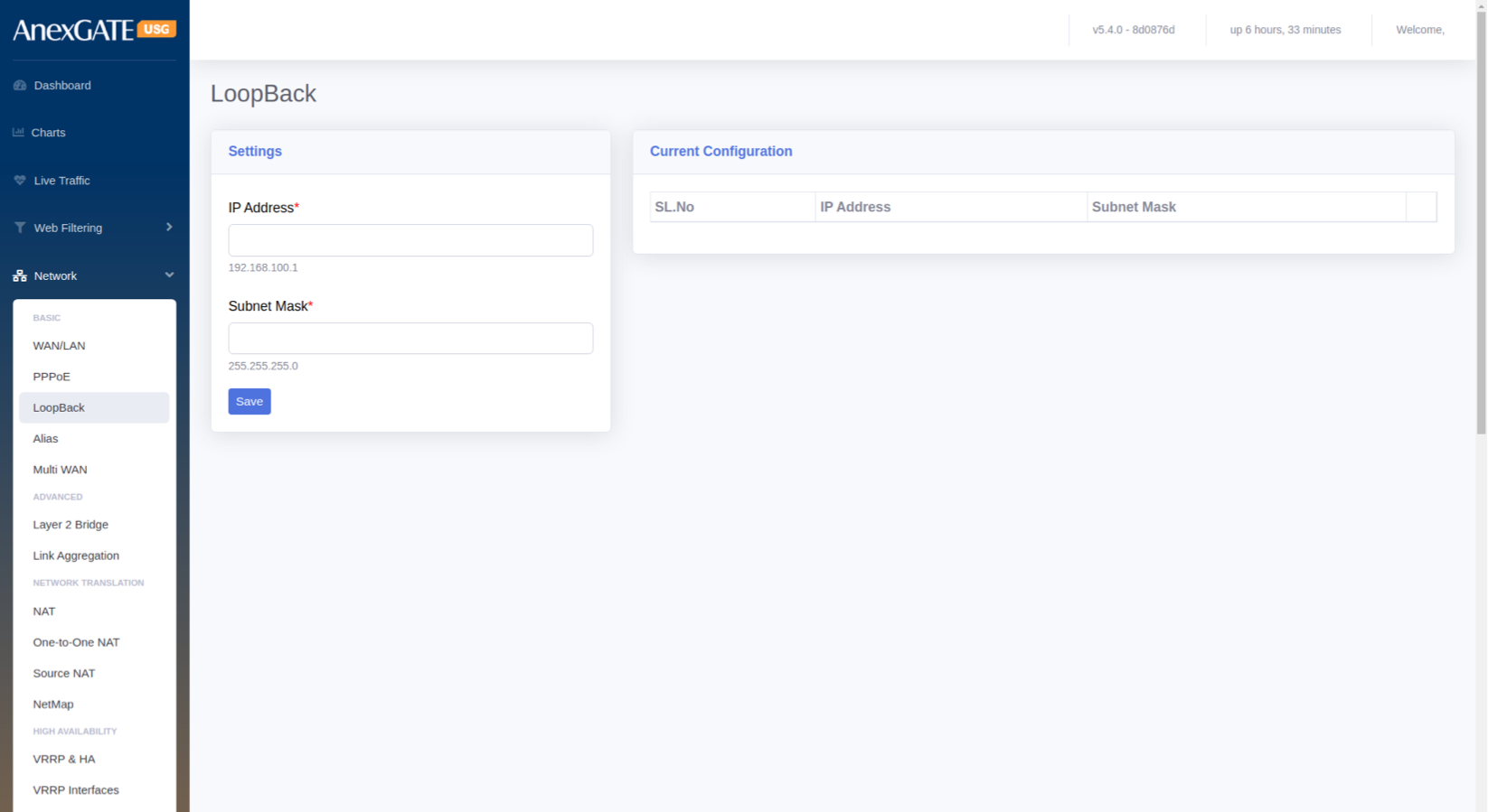
¶ 5.3 LOOPBACK
To configure Loopback Interface, Go to Network > Loopback.
¶ PARAMETERS
| ELEMENTS | DESCRIPTION |
|---|---|
| IP Address* | Assign Manual Loopback IP Address |
| Subnet Mask* | Assign Subnet Mask for the Loopback IP |
| SAVE | Save the loopback configuration settings. |
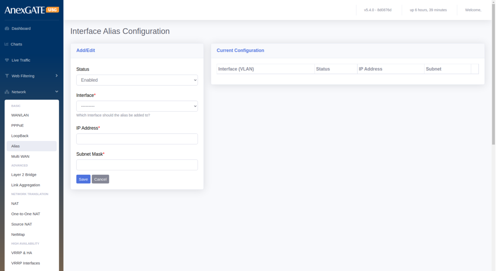
¶ 5.4 INTERFACE ALIAS CONFIGURATION
Alias IP can be used to configure Multiple WAN IPs on a single physical ethernet port, if they are all using a common gateway.
To configure an Alias IP, Go to Network > Alias.
¶ PARAMETERS
| ELEMENTS | DESCRIPTION |
|---|---|
| Status | Enable or Disable the Alias Interface. |
| Interface* | Select the interface to assign the Alias IP. |
| IP Address* | Enter the IP Address for the Alias IP to be configured. |
| Subnet Mask* | Enter the Subnet Mask for the Alias IP to be configured. |
| SAVE | Save the alias configuration settings. |
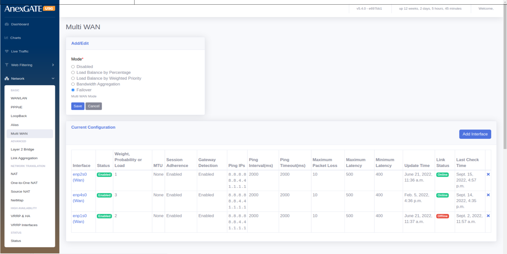
¶ 5.5 MULTI-WAN
USG Firewall has a functionality to configure and manage multiple internet WAN links which provide redudancy between Multiple Internet Connections. To configure Multi-WAN on multiple WAN links, Go to Network > Multi-WAN.
¶ MODES
| ELEMENTS | DESCRIPTION |
|---|---|
| Disabled | Disable the Multi WAN mode. |
| Load Balance by percentage | Select this mode, to Load Balance between multiple WAN links and assign percentage of data traffic for each link manually. |
| Load Balance by Weighted Priority |
Select this mode, to Load Balance between multiple WAN links and assign Weighted priority on each link. The data traffic is correspondant to the Weight provided on each Link. Higher the weight priority of the link, higher the data traffic flow on that link. |
| Bandwidth Aggregation | Select this mode to Load Balance by consolidating all the WAN links configured logically make them work in Active – Active Mode. |
| Failover |
Select this mode, to Load Balance between multiple WAN links and assign Priority on basis of Primary and secondary links. Basically an Active-Passive Mode. **Low priority number is considered to be primary link. Example: WAN1 – Priority 1 ( Primary) WAN2 – Priority 2 (Secondary) |
| SAVE | Save the Multi-WAN mode settings. |
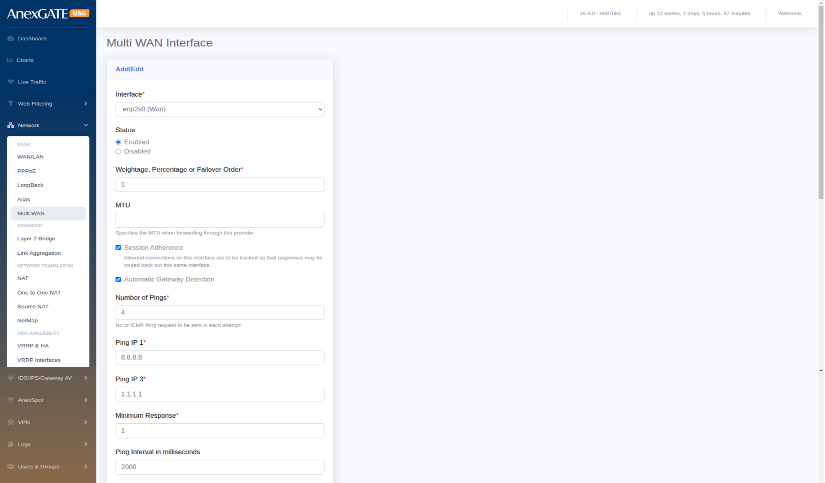
¶ 5.5.1 MULTI-WAN INTERFACE CONFIGURATION
To manage Multi-WAN, user must configure WAN interfaces under MutliWAN Interfaces before enabling Multi-WAN mode. To configure interfaces for Multi-WAN,
Go to Network > Multi-WAN > Add Interfaces.
¶ PARAMETERS
| ELEMENTS | DESCRIPTION |
|---|---|
| Add Interface | Click on Add interface below the Modes to configure Multi-WAN. |
| Interface | Select the interface to add in MultiWAN |
| Status | Enable or Disable the Multi-WAN interface |
| Weightage, Percentage or Failover order | Enter the priority number to associate the Interface with Multi-WAN |
| MTU | Specify the Maximum Transmission Unit (in Bytes) when forwarding the packets. |
| Session Adherence | Inbound connections on this interface are to be tracked so that responses may be routed back out this same interface. |
| Automatic Gateway Detection | Select this if the WAN link is dialled up over PPPoE directly into Firewall. |
| Number of Pings | Enter the number of pings to be ping’d by firewall until the link is considered to be Online or Offline. |
| Ping IP1, IP2, IP3 |
Enter the Remote IPs to be pinged on the WAN link. Example: 8.8.8.8, 8.8.4.4, 1.1.1.1 |
| Minimum Response | Enter the minimum number of response needed to consider the Link status as Online when the above pings are ping’d successfully for reachability. |
| Ping Interval in milliseconds | Time interval for each ping for reachability. Default = 2000ms |
| Timeout in milliseconds | Assign Timeout in milliseconds. Default = 2000ms |
| Check Performance | Select this for granular monitoring for WAN links. |
| Max Jitter Rate in % | Enter Maximum Jitter Rate in terms of percentage. Default = 10% |
| Max Packet Loss in % | Enter Maximum Packet loss in terms of percentage. Default=10% |
| Maximum Latency | Latency above which this link is not acceptable as online. |
| Minimum Latency | Latency below which this link is acceptable as online when it was previously offline |
| Trigger Failure Count* | Specify how many consecutive failures in link status to consider the link as offline. Default = 3 |
| Trigger Success Count* | Specify how many consecutive successes in link status to consider the link as online. Default = 3 |
| SAVE | Save the Multi-WAN interface configuration settings. |
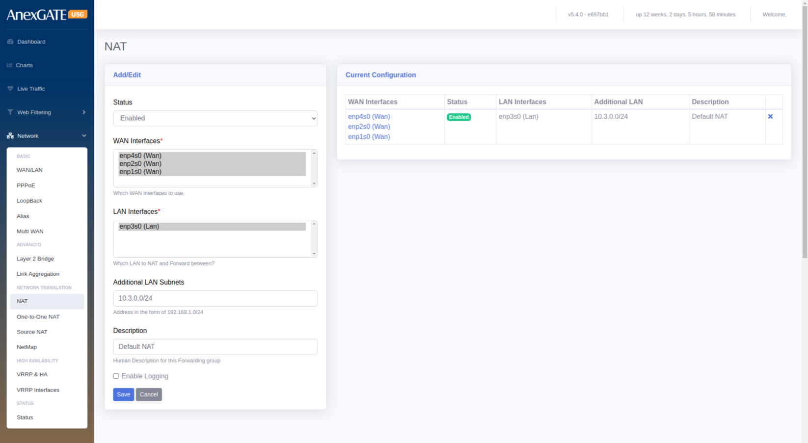
¶ NETWORK ADDRESS TRANSLATION
¶ 5.6 NAT
To configure Global NAT, Go to Network > NAT.
¶ PARAMETERS
| ELEMENTS | DESCRIPTION |
|---|---|
| Status | Enable or Disable NAT for the Interfaces selected. |
| WAN Interfaces* | Select WAN Interface used for NAT’ing with LAN Interface |
| LAN Interfaces* | Select LAN Interface used for NAT’ing with WAN Interface |
| Additional LAN Subnets | Enter the other LAN Network subnets which come under USG and are configured. |
| Description | Add a description for the NAT Configuration. |
| Enable Logging | Select this to get logs generated by the NAT Config. |
| SAVE | Save the NAT configuration settings. |
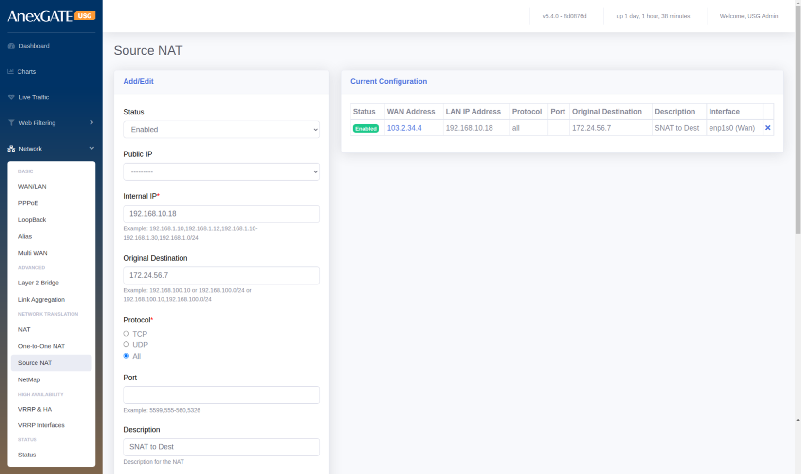
¶ 5.7 SOURCE NAT
To configure Source NAT, Go to Network > Source NAT.
¶ PARAMETERS
| ELEMENTS | DESCRIPTION |
|---|---|
| Status | Enable or Disable the Source NAT rule. |
| Public IP |
Select the Public IP Address if Alias IP has been assigned. **Use this parameter if the alias IP has been configured in Network > Alias. |
| Internal IP* |
Enter LAN IP or LAN Subnet of the system as a source. Example: 192.168.100.10 or 192.168.100.0/24 |
| Original Destination | Enter Destination IP to be NAT’d towards. |
| Protocol | Select the Protocol TCP, UDP or ALL to Source NAT to work with particular transport protocol. |
| Port | Select TCP/UDP Port Number to Source NAT with specific port (0-65535). Leave Blank to accept all ports. |
| Description | Add a description to the Source NAT rule. |
| Global IP | Enter the Public IP Address for outgoing traffic from LAN to use as source address when traffic is outbound. |
| Interface | Select the WAN Interface for the Global IP to be associated to be Source NAT’d. |
| SAVE | Save the Source NAT configuration settings. |
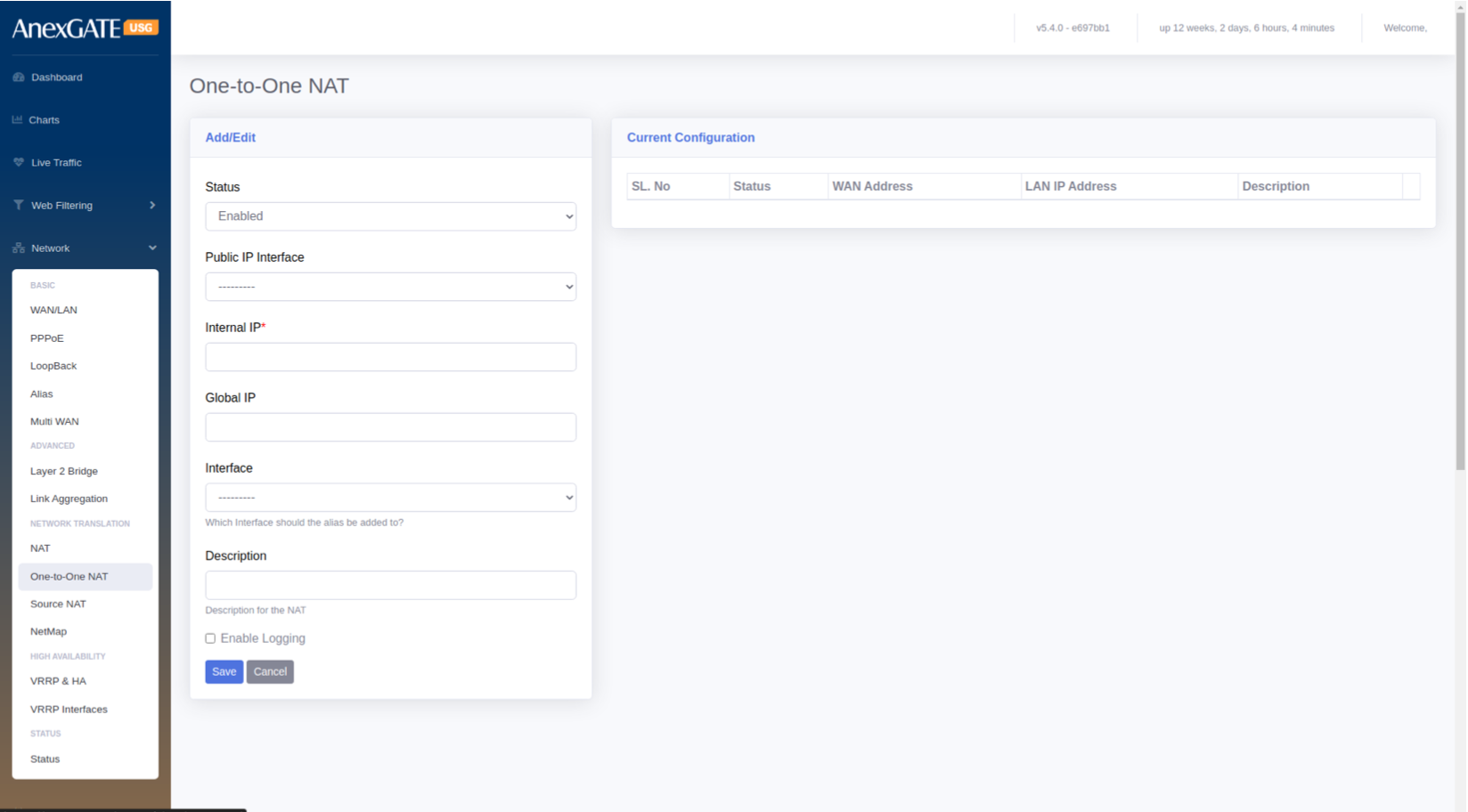
¶ 5.8 ONE TO ONE NAT
To configure One to One NAT, Go to Network > One to One NAT.
¶ PARAMETERS
| ELEMENTS | DESCRIPTION |
|---|---|
| Status | Enable or Disable the One to One NAT rule. |
| Public IP Interface |
Select the Public IP Address if Alias IP has been assigned. **Use this parameter if the alias IP has been configured in Network > Alias. |
| Internal IP* |
Enter LAN IP or LAN Subnet of the system as a source. Example: 192.168.100.10 or 192.168.100.0/24 |
| Global IP | Enter the Public IP Address for outgoing and incoming traffic from Public IP to use as source and destination address when traffic is Inbound and Outbound. |
| Interface | Select the WAN Interface for the Global IP to be associated with the interface for One to One NAT . |
| Description | Add a description to the One to One NAT rule. |
| SAVE | Save the One to One NAT configuration settings. |
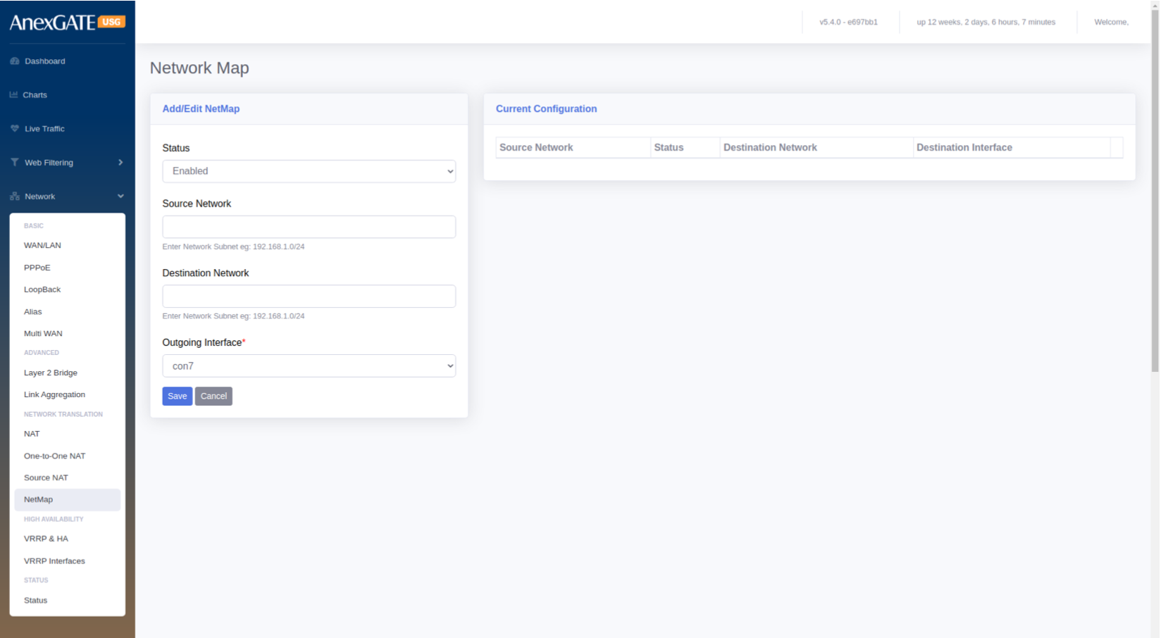
¶ 5.9 NETMAP
To configure Netmap, Go to Network > Netmap.
PARAMETERS
| ELEMENTS | DESCRIPTION |
|---|---|
| Status | Enable or Disable the status. |
| Source Network | Specify Source Network. |
| Destination Network | Specify Destination Network. |
| Outgoing Interface | Select the Outgoing Interface. |
| SAVE | Save the Netmap configuration settings. |
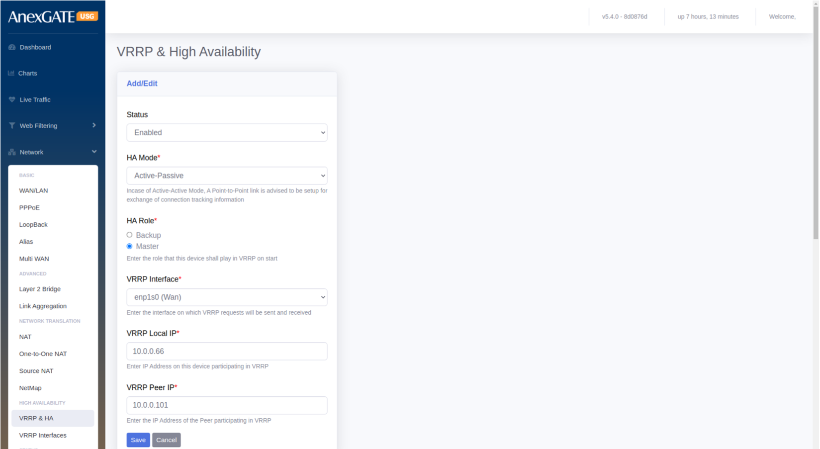
¶ 5.10 VRRP & HA (HIGH AVAILABILITY)
To configure VRRP & HA, go to Network > High Availability - VRRP & HA.
PARAMETERS
| ELEMENTS | DESCRIPTION |
|---|---|
| Status | Enable or Disable VRRP & HA status. |
| HA Mode |
Active – Active : Both USG Firewall will be in active – active state exchanging information. NOTE: Incase of Active-Active Mode, A Point-to-Point link is advised to be setup for exchange of connection tracking information. Active – Passive : One of the USG Firewall will be in active state and other USG will be in Passive where it receives only advertisements from the Active USG until it goes down. |
| HA Role |
Select the HA Role for the USG Firewall for VRRP on start Backup – The USG Firewall will be set as Backup of Firewall 1. Master – The USG Firewall will be set as Master of Firewall 2. |
| VRRP Interface | Enter the interface on which VRRP requests will be sent and received. |
| VRRP Local IP | Enter IP Address on this device participating in VRRP. |
| VRRP Peer IP | Enter the IP Address of the Peer participating in VRRP. |
| SAVE | Save the VRRP & HA configuration settings. |
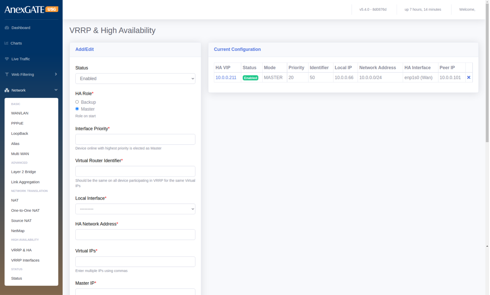
¶ 5.11 VRRP INTERFACES
To configure VRRP Interfaces, go to Network > High Availability – VRRP Interfaces.
PARAMETERS
| ELEMENTS | DESCRIPTION |
|---|---|
| Status | Enable or Disable the VRRP Interfaces. |
| HA Role* | Select the High Availability role for the Appliance to be started. |
| Interface Priority* | Specify the interface priority. Device Online with highest priority is elected as Master. |
| Virtual Router Identifier* | Specify Virtual Router Identifier. It should be same on all device participating in VRRP for the same Virutal IPs |
| Local Interface* | Select the Local Interface to configure HA |
| Virtual IPs* | Assign virtual IPs to the USG Firewall for HA |
| Master IP* | Specify the WAN IP of the Master USG Firewall |
| Back up IP* | Specify the WAN IP of the Backup USG Firewall |
| Preempt Higher Priority | Click this to enable Preempt Higher Priority which allows the higher priority machine to take over the master role, even when the higher priority machine comes back online. |
| SAVE | Save the VRRP Interface configuration settings. |
¶ NOTE:
VRRP Interfaces must be configured which will be performing as an redudant interfaces on other Firewall as well which will be participating as VRRP Redudant High Avaialibility of the device.
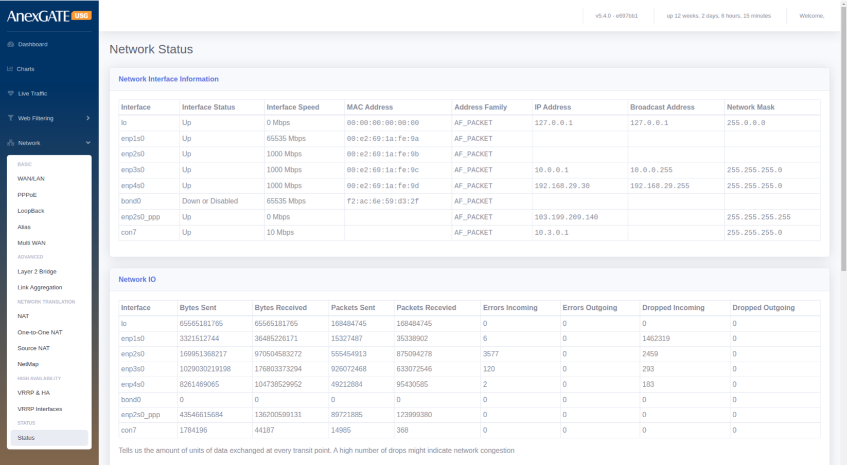
¶ 5.12 NETWORK STATUS
Network Interface Information
PARAMETERS
| ELEMENTS | DESCRIPTION |
|---|---|
| Interface | Displays the configured interface of the USG Firewall. |
| Interface Status | Displays the status whether the interface configured in UP or Down/Disabled. |
| Interface Speed | Displays the Interface speed in terms of Mbps. |
| MAC Address | Displays the MAC Address of the interface enabled. |
| Address Family | Displays as AF_Packet. |
| IP Address | Displays the IP address configured on the respective interfaces. |
| Broadcast Address | Displays the Broadcast address of IPs configured. |
| Network Mask | Displays the Subnet Mask of the IPs configured on the respective interfaces. |
¶ Network IO
The Network IO shows the amount of units of data exchanged at every transit point. A high number of drops might indicate network congestion.
PARAMETERS
| ELEMENT | DESCRIPTION |
|---|---|
| Interface | Displays the Interface configured on the USG Firewall. |
| Bytes Sent | Displays the traffic sent on the interfaces in terms of Bytes. |
| Bytes Received | Displays the traffic received on the interface in terms of Bytes. |
| Packets Sent | Displays the packet numbers send on the interfaces in terms of Bytes. |
| Packets Received | Displays the packet numbers received on the interfaces in terms of Bytes. |
| Errors Incoming | Displays error if any on the incoming traffic. |
| Errors Outgoing | Displays error if any on the outgoing traffic. |
| Dropped Incoming | Displays dropped traffic on the incoming traffic. |
| Dropped Outgoing | Displays dropped traffic on the outgoing traffic. |
6. IDS / IPS / GATEWAY AV
An IDS/IPS monitors traffic on your network, analyzes that traffic for signatures matching known attacks, and when something suspicious happens, you're alerted under Dashboard > Alerts.
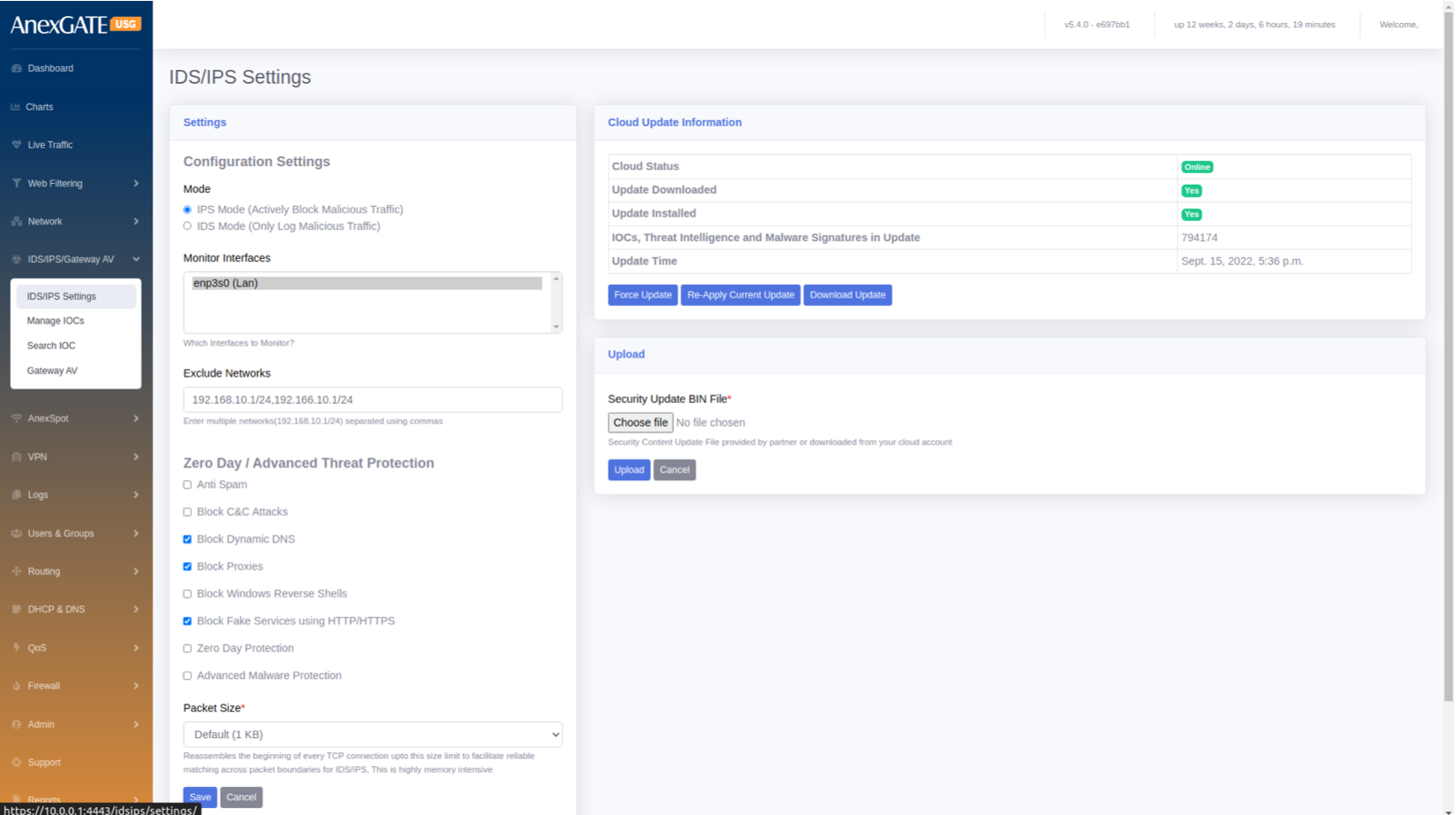
¶ 6.1 IDS/IPS SETTINGS
To configure IDS/IPS Settings, go to IDS/IPS/Gateway AV > IDS/IPS Settings.
PARAMETERS
| ELEMENTS | DESCRIPTION |
|---|---|
| Configuration Settings Mode |
Select Mode. IPS – To actively block Malicious Traffic IDS – To only log Malicious Traffic |
| Monitor Interfaces | Select the LAN Interfaces to monitor for malicious traffic. |
| Exclude Networks | Exclude Networks from being monitored for malicious traffic |
| Zero Day / Advance Threat Protection | Select and click from the list to block certain threats and reverse shells. |
| Packet Size | Select Packet Size to be scanned or monitored |
| SAVE | Save the IDS/IPS configuration settings. |
Cloud Update Information
IOCs, Threat Intelligence and Malware Signatures are updated and installed using cloud database online. To upload offline, Select the bin file which contains Security content update provided by AnexGATE or downloaded from cloud and click on Upload.
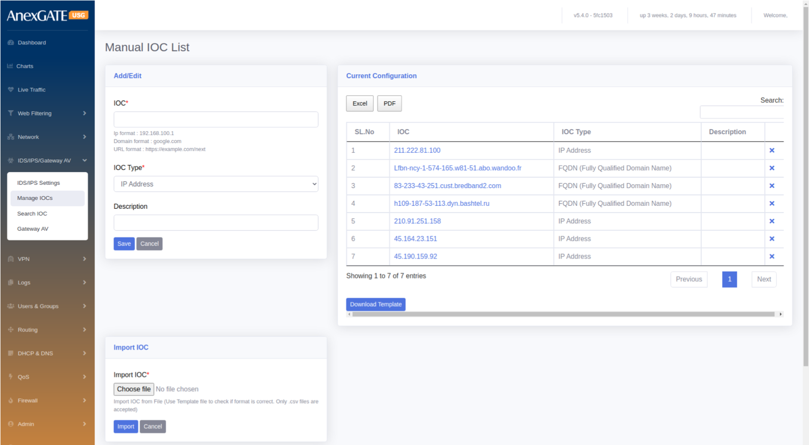
¶ 6.2 MANAGE IOC (Indicator of Compromise)
To configure and add IOC to the list, go to IDS/IPS/GATEWAY AV > Manage IOCs.
PARAMETERS
| ELEMENTS | DESCRIPTION |
|---|---|
| IOC* | Provide IOC format such as IP, Domain or URL. |
| IOC Type* | Select IOC Type resembling the specified IOC from below drop down list i.e., IP Address, FQDN (Fully Qualified Domain Name), URL, File Hash, Cert Hash. |
| Description | Add a description to the IOC list. |
| Import IOC | Import multiple IOCs from file. Download a template and fill the IOCs for the format to be correct. |
| SAVE | Save the IOC list configuration settings. |
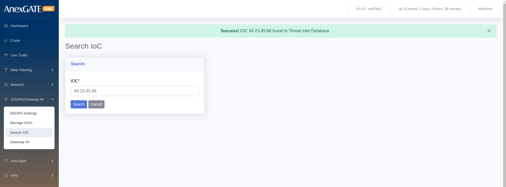
¶ 6.3 SEARCH IOC
To check if the Indicator of Compromis (IOC) is in the IDS/IPS Database.
Go to IDS/IPS/Gateway AV > Search IOC. Specify the IOC in terms of IP, domain or URL and click on Search.
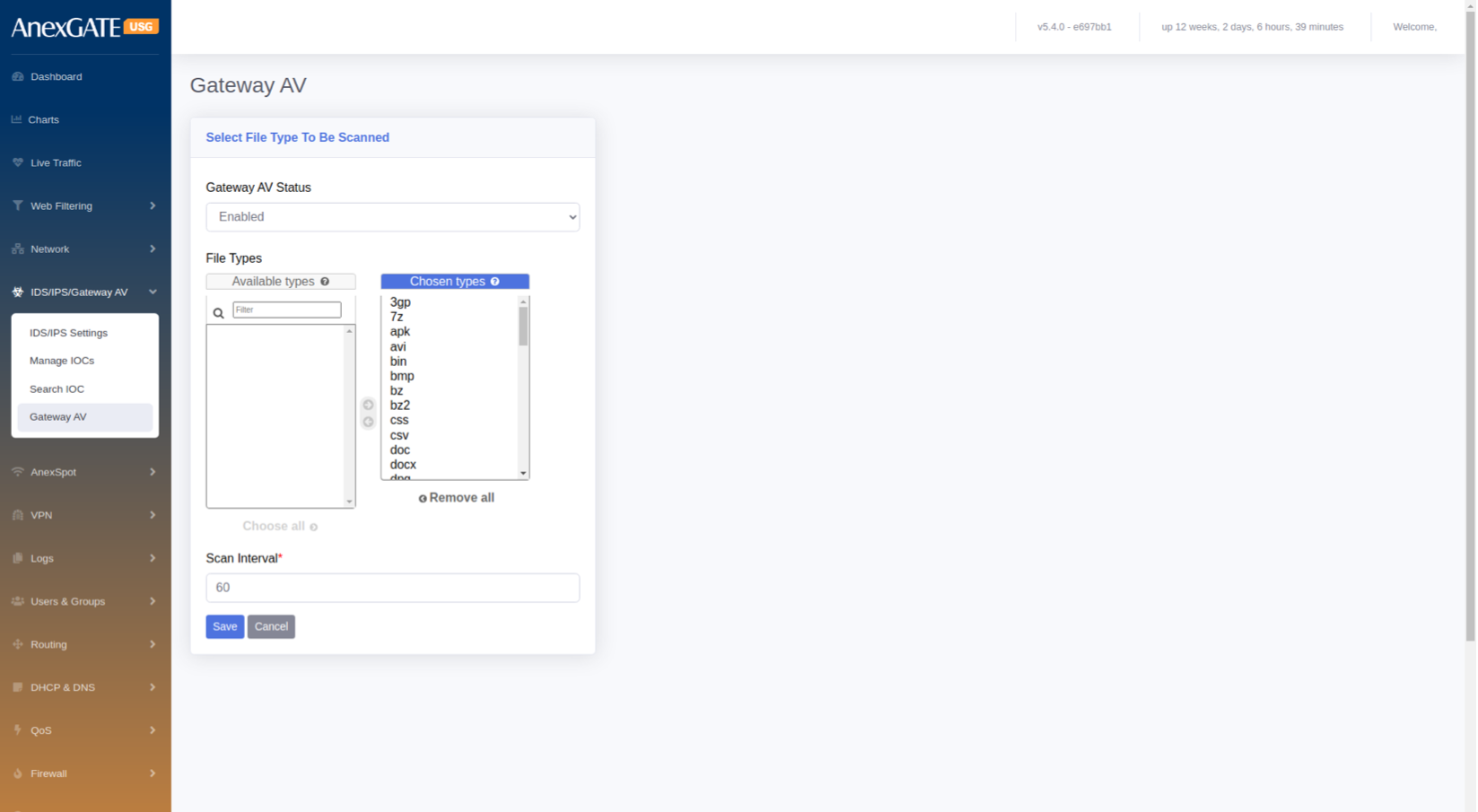
¶ 6.4 GATEWAY AV
To Configure Gateway AV Status, Go to IDS/IPS/Gateway AV > Gateway AV.
PARAMETERS
| ELEMENTS | DESCRIPTION |
|---|---|
| Status | Enable or Disable the Gateway AV status. |
| File types | Select the file types to be scanned by the USG Firewall |
| Scan Interval | Specify the Scan Interval in terms of Seconds. |
| SAVE | Save the Configuration. |
¶ 7. ANEXSPOT
AnexSPOT enables the feature to authenticate LAN users by using various authentication modes. Internet access to LAN users is allowed only after the user is successfully authenticated and authorised.
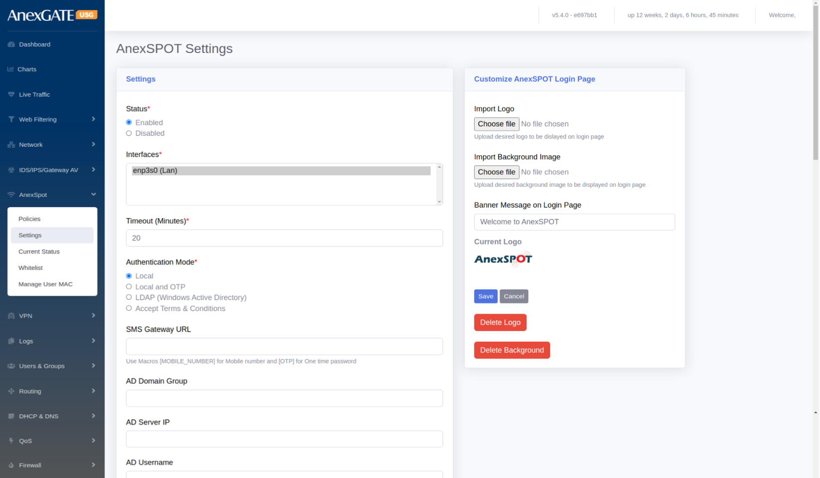
¶ 7.1 ANEXSPOT SETTINGS
To configure AnexSPOT, Go to AnexSPOT > Settings.
¶ PARAMETERS
| ELEMENTS | DESCRIPTION |
|---|---|
| Status* | Enable or Disable the AnexSpot Settings |
| Interfaces* | Select LAN interfaces to enable AnexSPOT on it |
| Timeout* | Enter the Session Timeout for Network Access once the user login through AnexSpot |
| Authentication Mode* |
Local - To authenticate users locally Local and OTP – To authenicate users locally using Mobile OTP LDAP (Windows Active Directory) Accept Terms & Conditions – To authenticate users using Disclaimer
|
| SMS Gateway URL | Add this if Local and OTP is chosen for authentication |
| AD Domain Group | Enter Active Directory (AD) Domain Group if LDAP is chosen for auth’n in AnexSPOT |
| AD Server IP | Enter AD Server IP if LDAP is chosen for authentication in AnexSPOT. |
| AD Username | Enter AD Username if LDAP is chosen for authentication in AnexSPOT. |
| AD Password | Enter AD Password if LDAP is chosen for authentication in AnexSPOT. |
| Exclude Sites | Add sites to exclude & bypass Authentication from AnexSPOT |
| Exclude Destination Network | Add Destination Network to exclude & bypass the Destination Ips and Entire Network Address pool. |
| Session Type |
Active Ping – Session is based on the Login Browser Tab. If the browser or the login tab is closed, the network access is denied. Time Based – Session is based on the Session Timeout mentioned. |
| Upload Bandwidth (Kbps) | Enter the Upload Bandwidth to be assigned in Kbps for the LAN Interface |
| Download Bandwidth (Kbps) | Enter the Download Bandwidth rate to be assigned in Kbps for the LAN Interface |
| Restrict Login to authorized devices | Select this if the user wants to be logged in to his device only with IP and MAC mentioned at USERS and GROUPS |
| Blacklist Device Types | Select the devices or OS to be blacklisted from network access |
| Device type Bypass Users | Select the user to bypass the above blacklist restriction on Devices |
| SAVE | Save the anexspot configuration Settings |
NOTE:
Enabling the AnexSPOT Settings will automatically DROP the LAN to WAN policy in Firewall > Policies which will block the network access for unauthenticated AnexSPOT Users.
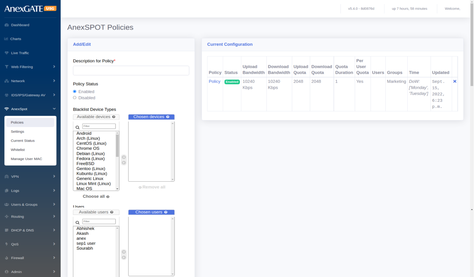
¶ 7.2 ANEXSPOT POLICY
To configure AnexSPOT Policy, Go to AnexSPOT > Policy.
¶ PARAMETERS
| ELEMENTS | DESCRIPTION |
|---|---|
| Description for Policy* | Add a description to the policy |
| Policy Status | Enable or Disable the policy. |
| Blacklist Device Types | Block the devices (Ex: Linux, Windows, Android or MAC) from accessing the network using AnexSpot. |
| Users | Select Users for the policy to be applied. |
| Groups | Select Groups for the policy to be applied. |
| Upload Bandwidth Limit (Kbps) | Enter Upload Bandwidth Limit in Kbps in order to restrict the Bandwidth speed. |
| Download Bandwidth Limit (Kbps) | Enter Download Bandwidth Limit in Kbps in order to restrict the Bandwidth speed. |
| Upload Data Quota | Assign the Upload QuotaData in MB to be alloted for the policy |
| Download Data Quota | Assign Download Quota in MB to be alloted for the policy |
| Quota Duration (In Days) | Enter Duration of Quota to come into effect. For instance, Once the Quota is over, it will take around 1 day to reset the policy. 0 = unlimited. |
| Per User Quotas | Tick this if the Quota must be assigned to the users individually rather than the whole policy. |
| From Date/Time | Assign Date/Time for the policy to be applied and take effect at start. |
| To Date/Time | Assign Date/Time for the policy to be applied till the end. |
| Days of Week | Select specific days for the policy to be applied for the number of days. |
| SAVE | Save the anexspot policy configuration settings. |
¶ 7.3 ANEXSPOT WHITELIST
The admin user can specify which user can bypass authentication by adding IP Address or MAC Address or both under AnexSPOT Whitelist.
To configure AnexSPOT Whitelist, Go to AnexSPOT > Whitelist.
¶ PARAMETERS
| ELEMENTS | DESCRIPTION |
|---|---|
| IP ADDRESS | Add IP Address of the System-PC to bypass the AnexSpot Login Authentication to that particularly IP assigned to any System-PC. |
| MAC ADDRESS |
Add MAC Address of the System-PC to bypass the AnexSpot Login Authentication. **Mac Address Format – aa:bb:cc:dd:ee:ff / aa:bb:01:cc:05:22 |
| SAVE | Save the anexspot whitelist configuration settings. |
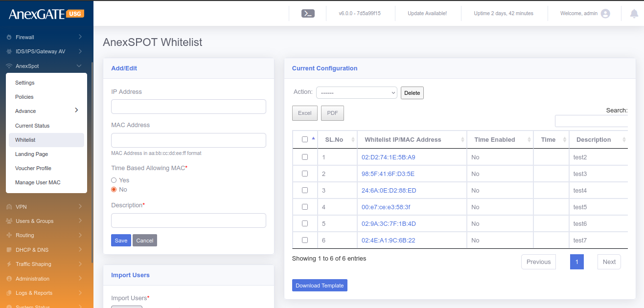
NOTE:
1. Only IP Address or MAC Address can be assigned to bypass AnexSpot on any System-PC.
2. Both IP and MAC Address can be assigned as well.
**Clicking on the Blue Highlighted IP Address / Mac Address will display the AnexSpot Whitelist configuration and can be edited.
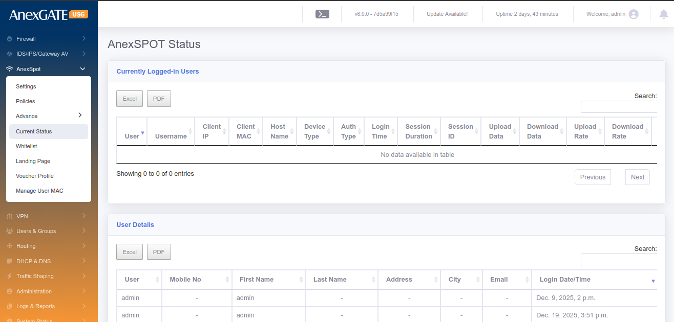
¶ 7.4 CURRENT STATUS
Current Status displays logged in users under AnexSPOT along with other attributes of the logged in user mentioned below.
¶ PARAMETERS
| ELEMENTS | DESCRIPTION |
|---|---|
| User | Displays user (first name) configured in users under Users & Groups. |
| Username | Displays Anexspot username used to login. |
| IP Address | Displays the IP Address assigned to the user automatically. |
| MAC Address | Displays the MAC Address of the endpoint used to login by user. |
| Host Name | Displays the Hostname of the endpoint. |
| Device Type | Displays the device type of the user endpoint. Ex: Windows or Android. |
| Login Time | Displays the logged in time of the user. |
| Session Duration | Displays the session duration alloted to the user before he gets logged out automatically after session timeout. |
| Download | Displays the Download statistitics usage by the user. |
| Upload | Displays the Upload statistics usage by the user. |
| Logout | Click icon to Force logout the user from the AnexSPOT. |
¶ 8. VPN (VIRTUAL PRIVATE NETWORK)
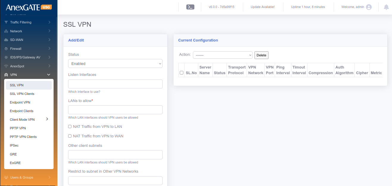
¶ 8.1 SSL VPN
SSL VPN is a VPN Protocol used to facilitate a secure VPN tunnel between two points in a network. This can be used in communication with other private networks or VPN Clients and makes sure that the data sent over the internet to be encrypted and private.
To configure SSL VPN, Go to VPN > SSL VPN.
¶ Pre-Requisite:
1. Create a “VPN” zone at FIREWALL > ZONES (Save it without selecting any physical interfaces).
2. Create Firewall Policies,
LAN to VPN - Select Source – LAN and Destination – VPN, Save the Policy.
VPN to LAN - Select Source – VPN and Destination – LAN, Save the Policy.
VPN to Firewall - Select Source – VPN and Destination – FW, Save the Policy.
¶ PARAMETERS
| ELEMENTS | DESCRIPTION |
|---|---|
| STATUS | Enable / Disable the SSL VPN |
| Listen Interfaces | Select Interfaces to listen on respective WAN or leave blank to listen on all WAN Interfaces |
| LANs to allow* | Select LAN Subnet to be allowed to reachable while on VPN from remote VPN clients. |
| NAT Traffic from VPN to LAN | NATs the data traffic from VPN to LAN |
| NAT Traffic from VPN to WAN | NATs the data traffic from VPN to WAN |
| Other Client Subnets | Select other client subnets from the VPN client list |
| Restrict to subnet to other VPN networks | Allow multiple WAN/LAN subnets to communicate with VPN clients other than Firewall LAN |
| VPN Server name* | Assign a name to the SSL VPN Server. |
| Transport Protocol for VPN* |
TCP – Send/Receive DATA in sequence with Acknowledgement UDP – Send/Receive data without Acknowledgement |
| Zones | **Create a VPN zone in Firewall > Zones before configuration of SSL VPN |
| Cipher | Choose Cipher to Encrypt and Dycrypt the data traffic passed through VPN tunnel. Example: AES-128-CBC |
| Auth. Algorithm | Choose Authentication Algorithm to verify the authenticity between VPN server and client to establish a tunnel. Example: SHA1 |
| VPN Network IP Space* | Provide specific network address for SSL VPN. Example: 10.10.0.0, 172.16.0.0, 192.168.0.0 |
| VPN Network Subnet Mask | Provide a Subnet Mask to the network address above according to the host range. Example: 255.255.255.0, 255.255.0.0 |
| Port for VPN Service | Open a TCP/UDP port to listen. Default = 1194 |
| Client Primary & Secondary DNS | Assign DNS to the VPN clients (optional). |
| Keepalive Ping | Ping VPN clients to check if connected. Default = 10 |
| Keepalive Timeout | Timeout interval of VPN client to check if connected. Default = 120 |
| Enable Compression | LZO compression used for lossless data compression |
| Route Metric | Assign a metric to VPN route if needed |
| SAVE | Save the ssl vpn configuration settings |
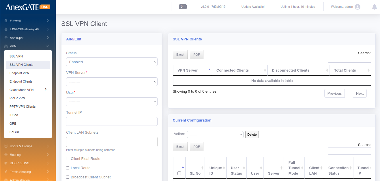
¶ 8.2 SSL VPN CLIENTS
To configure SSL VPN Clients, Go to VPN > SSL VPN Clients.
¶ Pre-Requisite:
1. Create a group specifically for VPN users in “USERS and GROUPS”. Example: vpn
2. Create users for the “vpn” group.
¶ PARAMETERS
| ELEMENTS | DESCRIPTION |
|---|---|
| STATUS | Enable/Disable the SSL VPN Clients |
| VPN Server* | Select the VPN Server instance created in SSL VPN tab. |
| User* | Select the users from VPN group. Example: vpnuser (0.0.0.0) |
| Tunnel IP |
1. Enter a tunnel IP in order to get the same static tunnel IP everytime when the VPN is connected. 2. Leave it blank, if the remote client tunnel IP must be random everytime when the VPN is connected as per the subnet provided by the SSL VPN Server. |
| Client LAN Subnets | Enter the LAN subnet Network Address with Network subnet mask (Example: 192.168.1.0/24) |
| Client Float Route | Selecting this will Add or Remove route of VPN, according to the connectivity status of VPN. |
| Passphrase | Passphrase added here must be same when setting up VPN at the Remote client. This is used specifically for Strict Authentication. |
| Full Tunnel Mode | Click on this to configure the client in Full Tunnel Mode |
| SAVE | Save the vpn client configuration settings |
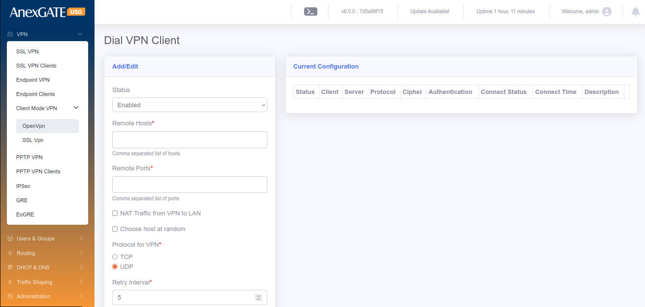
¶ 8.3 CLIENT MODE VPN
Client Mode VPN is used when the USG Firewall itself is considered to be a client and connect towards VPN Server in order to access the remote LAN network securely on VPN.
To configure Client Mode VPN, Go to VPN > Client Mode VPN.
¶ Pre-Requisite:
1. Create a “VPN” zone at FIREWALL > ZONES (Save it without selecting any physical interfaces).
2. Create Firewall Policies,
LAN to SSLVPN - Select Source – LAN and Destination – SSLVPN, Save the Policy.
SSLVPN to LAN - Select Source – SSLVPN and Destination – LAN, Save the Policy.
SSLVPN to Firewall - Select Source – SSLVPN and Destination – FW, Save the Policy.
3. Must have a client ovpn file provided by a VPN server to fill in the parameters of Dial VPN client.
NOTE:
Each VPN Zone must be configured individually with its own unique keyword as instructed to avoid conflicts or overlapping of Network Subnets for SSL VPN, Client Mode VPN, PPTP VPN and IPSec.
¶ PARAMETERS
| ELEMENTS | DESCRIPTION |
|---|---|
| STATUS | Enable/Disable the Dial VPN Client |
| Remote Hosts* | Enter Public Static IP Address of the VPN server. |
| Remote Ports* | Enter Public Port added to the VPN Server. Example: 1194 |
| NAT Traffic From VPN to LAN | Select this to NAT traffic from VPN to LAN. |
| Choose host at random | (Optional) Choose hosts at random. Or Leave it blank. |
| Protocol for VPN* | Select TCP or UDP as protocol as per configuration in VPN Server. |
| Retry Interval | Time Interval in secs, which the VPN client retries to connect if disconnected. |
| Maximum retry count |
Number of times the VPN client tries to connect to VPN Server. Default is 0 which means unlimited/forever. |
| Zones* | Select VPN as a zone, which is created in Firewall > Zones |
| Cipher | Choose Cipher to Encrypt and Dycrypt the data traffic passed through VPN tunnel. Example: AES-128-CBC |
| Auth Algorithm | Choose Authentication Algorithm to verify the authenticity between VPN server and client to establish a tunnel. Example: SHA1 |
| Description | Add a Description to differentiate multiple Dial VPN clients. |
| LANs to allow | Allow LAN side of the USG Firewall to able to communicate with VPN Server. |
| Persist Key | Select this to not to remove the VPN Client Keys after disconnection. |
| Persist Tunnel | Select this to not to remove the tunnel interface if the VPN Server gets disconnected. |
| Enable Compression | LZO compression is used for lossless compression of the data sent through the VPN Tunnel. |
| TLS Verify Client | Must be selected if the VPN Server has added TLS key as a layer of security. |
| CA Certficate* | Enter the CA Certificate value <ca>from ---Begin Certicate--- till ---End Certificate--- in the ovpn file provided by VPN Server. |
| Client Certificate* | Enter the Client Certificate value <cert> from---Begin Certicate --- till ---End Certificate--- in the ovpn file provided by VPN Server. |
| Client Key* | Enter <key> Key value from ---BEGIN PRIVATE KEY--- till ---END PRIVATE KEY--- in the ovpn file provided by VPN Server. |
| TLS Key | Enter <tls-auth> Key value from ---BEGIN OpenVPN Static Key V1--- till ---END OpenVPN Static key V1--- from the ovpn file. |
| Passphrase | Enter Passphrase for Authentication as per the VPN Server. |
| SAVE | Save the client mode vpn configuration settings. |
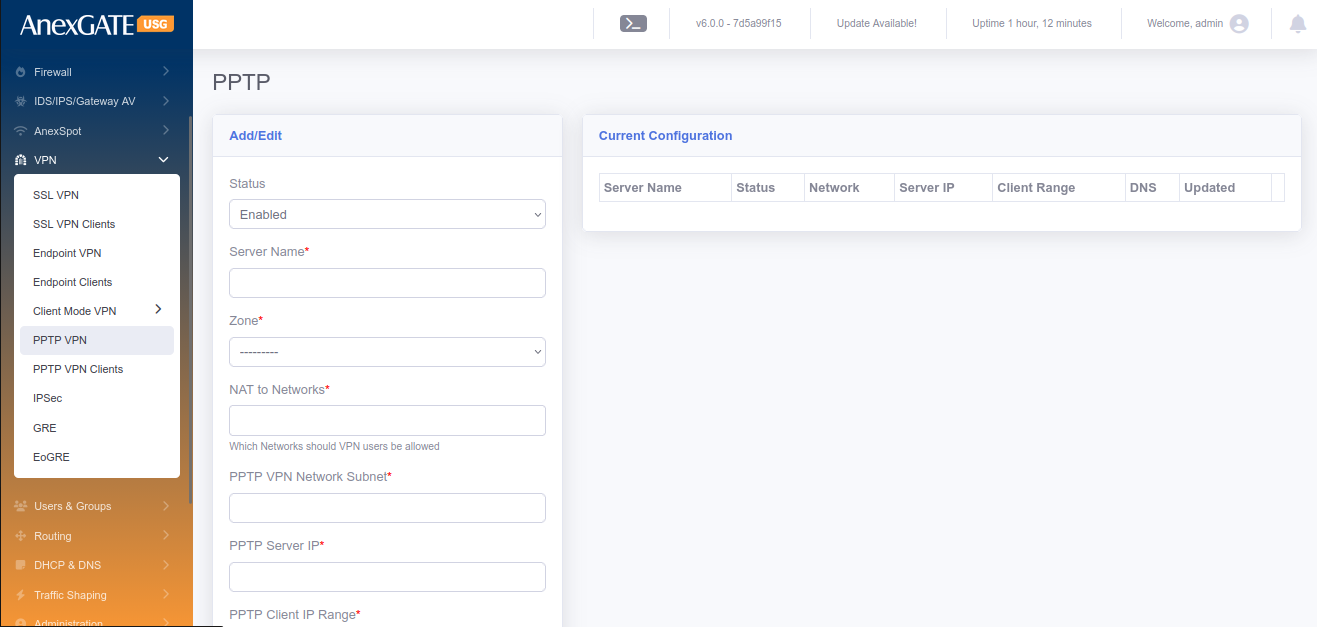
¶ 8.4 PPTP VPN
PPTP (Point-To-point Tunneling Protocol) is a VPN protocol that can be used to ensure proper communications between a VPN client and VPN Server. PPTP VPN does not provide any encryption while the data traffic is sent via VPN Tunnel.
To configure PPTP VPN Server, Go to VPN > PPTP VPN.
¶ Pre-Requisite:
1. Create a “PPTP” zone at FIREWALL > ZONES (Save it without selecting any physical interfaces).
2. Create Firewall Policies,
LAN to PPVPN - Select Source – LAN and Destination – PPVPN, Save the Policy.
PPVPN to LAN - Select Source – PPVPN and Destination – LAN, Save the Policy.
PPVPN to Firewall - Select Source –PPVPN and Destination – FW, Save the Policy.
NOTE:
Each VPN Zone must be configured individually with its own unique keyword as instructed to avoid conflicts or overlapping of Network Subnets for SSL VPN, Client Mode VPN, PPTP VPN and IPSec.
¶ PARAMETERS
| ELEMENTS | DESCRIPTION |
|---|---|
| STATUS | Enable/Disable the PPTP VPN. |
| Server Name* | Assign a name for PPTP Server. |
| Zone* | Select PPTP Zone. |
| NAT To Networks* | Select the interfaces to NAT. |
| PPTP VPN Network Subnet* | Assign PPTP VPN Network Subnet. Ex: 10.10.0.0/24 |
| PPTP Server IP* | Assign an IP for PPTP Server. Ex: 10.10.0.1 |
| PPTP Client IP Range* | Assign a PPTP Client Range. Ex: 10.10.0.10-20 |
| Primary Client DNS* | Assign Primary Client to resolve DNS. |
| Secondary Client DNS* | Assign Secondary Client IP to resolve DNS. |
| SAVE | Save the PPTP VPN Server configuration settings |
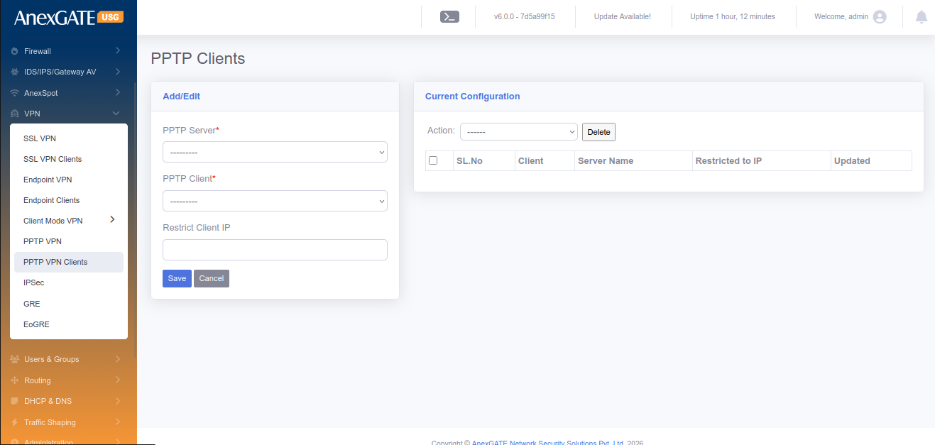
¶ 8.5 PPTP VPN CLIENTS
To configure Client Mode VPN, Go to VPN > PPTP VPN.
¶ PARAMETERS
| ELEMENTS | DESCRIPTION |
|---|---|
| PPTP Server* | Select PPTP Server configured in VPN > PPTP VPN. |
| PPTP Client | Select the user for PPTP Client. |
| Restrict Client IP | Assign IP to the PPTP Client user |
| NAT To Networks* | Select the interfaces to NAT. |
| SAVE | Save the PPTP Client configuration settings. |
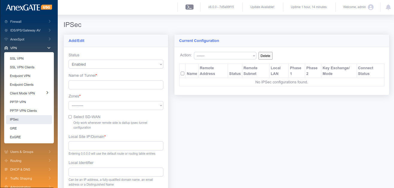
¶ 8.6 IPSec
IPSec VPN is a open standard VPN protocol that uses the IPSec protocol suite to establish and maintain the privacy of communication between devices by encrypting the data traffic. IPSec is perfectly suited for site-to-site ensuring privacy of Network communications between other vendor devices.
To configure IPSec, Go to VPN > IPSec.
¶ Pre-Requisite:
1. Create a “VPN” zone at FIREWALL > ZONES (Save it without selecting any physical interfaces).
2. Create Firewall Policies,
LAN to IPVPN - Select Source – LAN and Destination – IPVPN, Save Policy.
IPVPN to LAN - Select Source – IPVPN and Destination – LAN, Save Policy.
IPVPN to Firewall - Select Source – IPVPN and Destination – FW, Save Policy.
NOTE:
Each VPN Zone must be configured individually with its own unique keyword as instructed to avoid conflicts or overlapping of Network Subnets for SSL VPN, Client Mode VPN, PPTP VPN and IPSec.
¶ PARAMETERS
| ELEMENTS | DESCRIPTION |
|---|---|
| STATUS | Enable or Disable the IPSec VPN Instance. |
| Name of Tunnel* | Provide a name for the IPSec Tunnel Instance |
| Local Interface* | Select WAN Interface configured in the USG Firewall. To select multiple WAN Interfaces, press CTRL and select other interfaces. |
| Zones* | Select VPN zone as a zone for IPSec Tunnel Instance. |
| Local Site IP/Domain* |
Enter Public IP address or Domain name (at USG Firewall). Entering 0.0.0.0 will use the default route or routing table entries. |
| Local Identifier |
Enter Public IP address or Keyword for the identification of IPSec Tunnel Instance. **Identifier can be an IP address, a fully-qualified domain name, an email address or a Distinguished Name. |
| Local Subnets* |
Enter local LAN Subnet of the USG Firewall. Example: 192.168.100.0/24,192.168.200.0/24 Enter Multiple LAN Subnets using comma as shown in example. |
| IKE Version | Select IKE v1 or IKE v2 for IPSec |
| Key Exchange Mode | Select Main or Aggressive Mode. |
| Key Life* | Mention Key Life in terms of “seconds” |
| IKE Key Lifetime* | IKE Key Lifetime in terms of “seconds” |
| Phase 1 DH Group* |
Select Diffie-Hellman Group for Key Exchange Process. Consists of MODP, ECP and curve groups for secure Key Management. |
| Phase 1 Proposal* | Select IPSec proposal Algorithm for IKE negotiation with Remote IPSec peer. Example: 3DES/SHA1, AES-128/SHA-256 |
| Phase 2 Mode* |
Select one of the two protocols; ESP – Encapsulation Security Payload AH – Authentication Header. |
| Perfect Forward Secrecy | Perfect Forward Secrecy (PFS) must be selected if Phase 2 DH Group needs to be configured at remote side. |
| Phase 2 Proposal* | Select IPSec proposal Algorithm for negotiation with Remote IPSec peer to establish an IPSec tunnel. Example: 3DES/SHA1, AES-128/SHA-256 |
| Keepalive Frequency* | Mention Keepalive Frequency to specify the amount of time that the peer waits for traffic from its destination peer before sending a dead-peer-detection (DPD) request packet. |
| Dead Peer Detection | Select Dead Peer Detection (DPD) to detect the availability of Remote IPSec Peer. |
| DPD Action |
Select DPD Action. Hold - Hold installs a trap policy, which will catch matching traffic and tries to re-negotiate the connection on demand. Clear – Clear removes policy and state entries from the kernel. Restart - Restart will immediately trigger an attempt to re-negotiate the connection. |
| DPD Delay | Mention DPD Delay in terms of seconds. |
| DPD Timeout | Mention DPD Timeout in terms of seconds. |
| Keyring retry count* |
Specifies the maximum number of retries before the tunnel is removed. 0 = Unlimited / Forever. |
| Remote Identifier |
Enter Public IP address or Keyword for the identification of IPSec Tunnel Instance. **Identifier can be an IP address, a fully-qualified domain name, an email address or a Distinguished Name. |
| Remote Site IP* |
Enter Public IP address or Domain name of remote side Firewall. Entering 0.0.0.0 will use the default route or routing table entries. |
| LAN Subnet on Remote* |
Enter remote LAN Subnet of remote side Firewall. Example: 192.168.100.0/24,192.168.200.0/24 Enter Multiple LAN Subnets using comma as shown in example. |
| Passphrase* | Enter Pre-Shared key Passphrase for Authenticity between Site to Site VPN. |
| Force UDP Encapsulation (Optional) | Click on the force UDP encapsulation for ESP packets even if no NAT situation is detected. |
| DSCP Tag (Optional) | Click on this to enable Differentiated Services Code Point (DSCP) marking on outgoing (egress) IP packet traffic for a given protocol with a default or user-provided DSCP code. DSCP marking is a mechanism for classifying and managing network traffic |
| Tunnel Priority (Optional) | Value indicating priority when multiple tunnel with same local/remote subnet. Priority Range is from 40 to 100 |
| Install Routing Policy | Installs Routing policy for the IPSec Policy. Bydefault it is selected. |
| Global Tunnel Traffic | Select this if multiple subnets are at remote side in a single SA. |
| By passed Subnets | Enter network address with subnets to bypass when Global Tunnel Traffic is selected. |
| SAVE | Save the IPSec configuration settings |
¶ 9 LOGS
¶ DEVICE LOGS
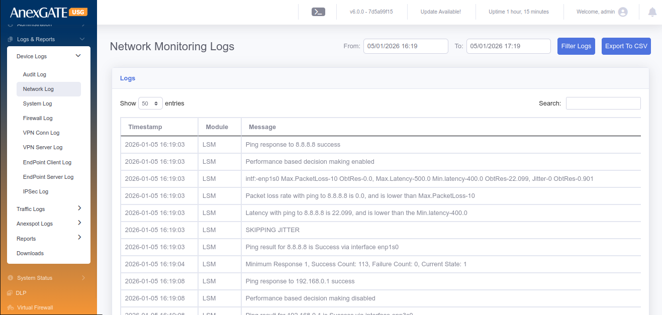
¶ 9.1 NETWORK LOG
Network Log displays the monitoring of the link state of WAN links configured on the USG Firewall.
To check Network logs, Go to Logs > Network Log.
NOTE: The logs will be displayed only if there are multiple wan links are configured and MultiWAN state is enabled.
¶ 9.2 DEVICE LOG
Device Log displays the events handled in the USG Firewall.
To check Device logs, Go to Logs > Device Log.
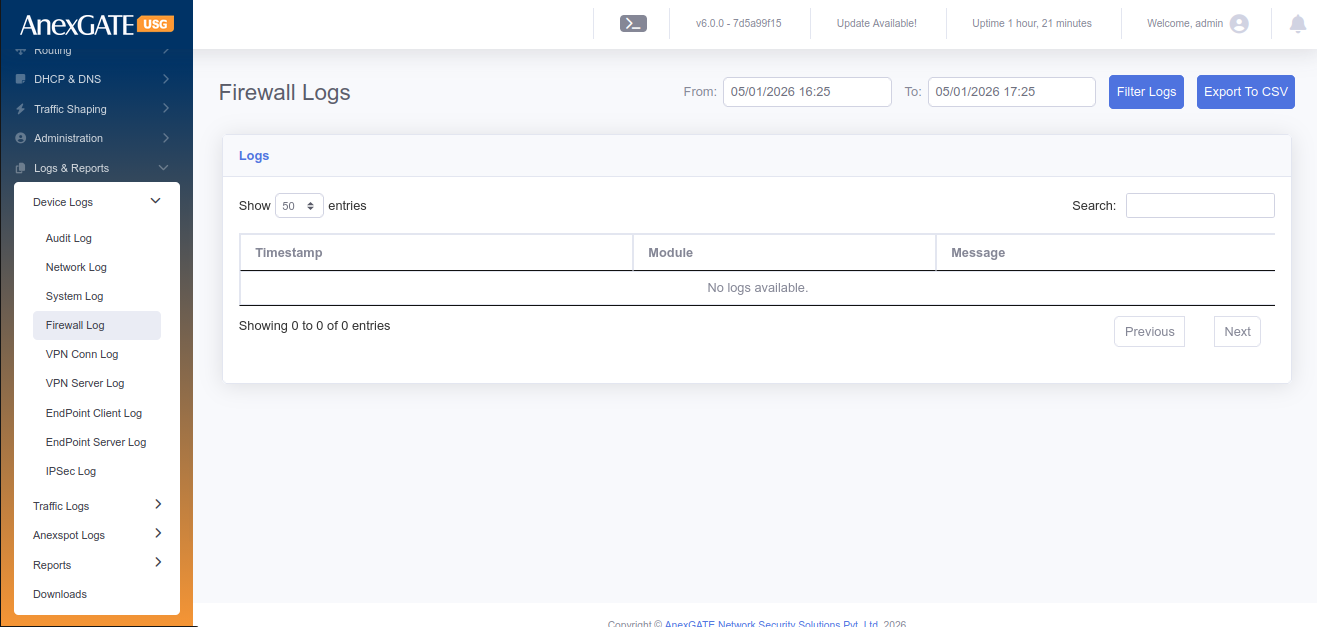
¶ 9.3 FIREWALL LOG
Firewall log displays the Inbound and Outbound traffic based on Source IP/Port and Destination IP/Port.
To check Firewall logs, Go to Logs > Firewall Log.
NOTE: Enable Logging option must be checked (ticked) under Firewall Policy or Rule in order to receive the Firewall Logs.
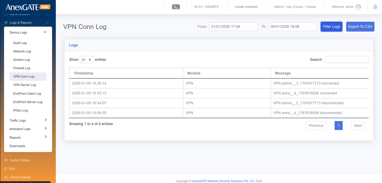
¶ 9.4 VPN LOG
VPN log display the event of the user being connected and disconnected.
To check the VPN Log, Go to Logs > VPN Log.
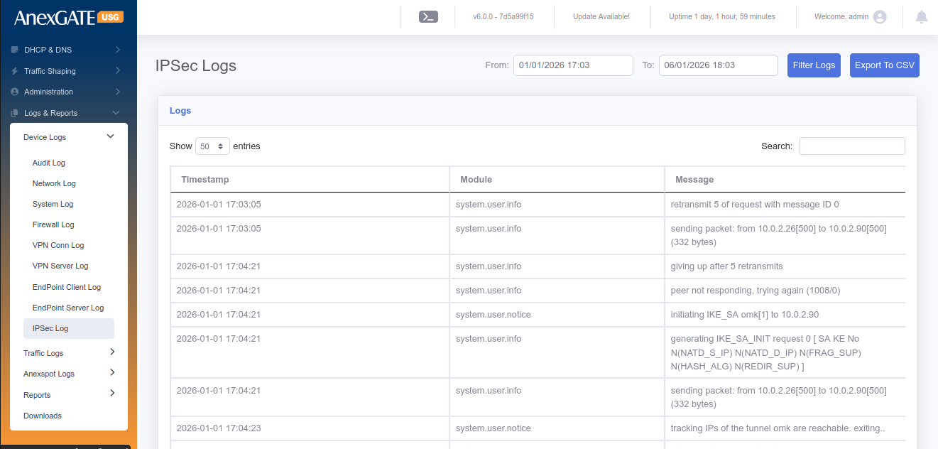
¶ 9.5 IPSEC LOG
IPSec log displays the events being handled during establishment of IPSec Tunnel between Local and Remote networks. The same logs can be reffered to troubleshoot the connectivity of IPSec Tunnel.
To check IPSec Logs, Go to Logs > IPSec Log.
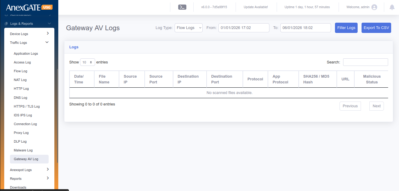
¶ 9.6 GATEWAY AV LOG
Gateway AV acts as an anti-virus which displays the events of the file being logged as malicious if it is suspected to contain the malware entity. The file will be blocked and the same will be displayed in the Gateway AV Log.
To check the Gateway AV Logs, Go to Logs > Gateway AV Log.
¶ TRAFFIC LOGS
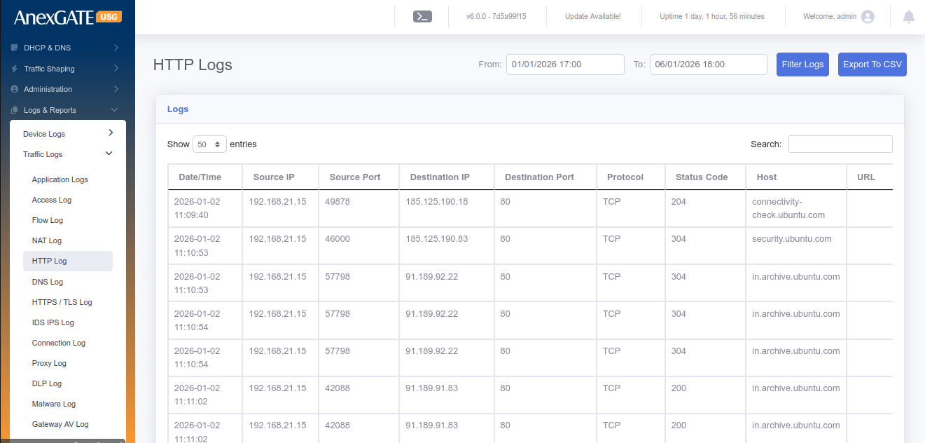
¶ 9.7 HTTP LOG
HTTP Log displays the event of the user accessing the website with the parameters of IP originating from, Destination Address being reach to along with the timestamp.
To check the HTTP Log, Go to Logs > HTTP Log.
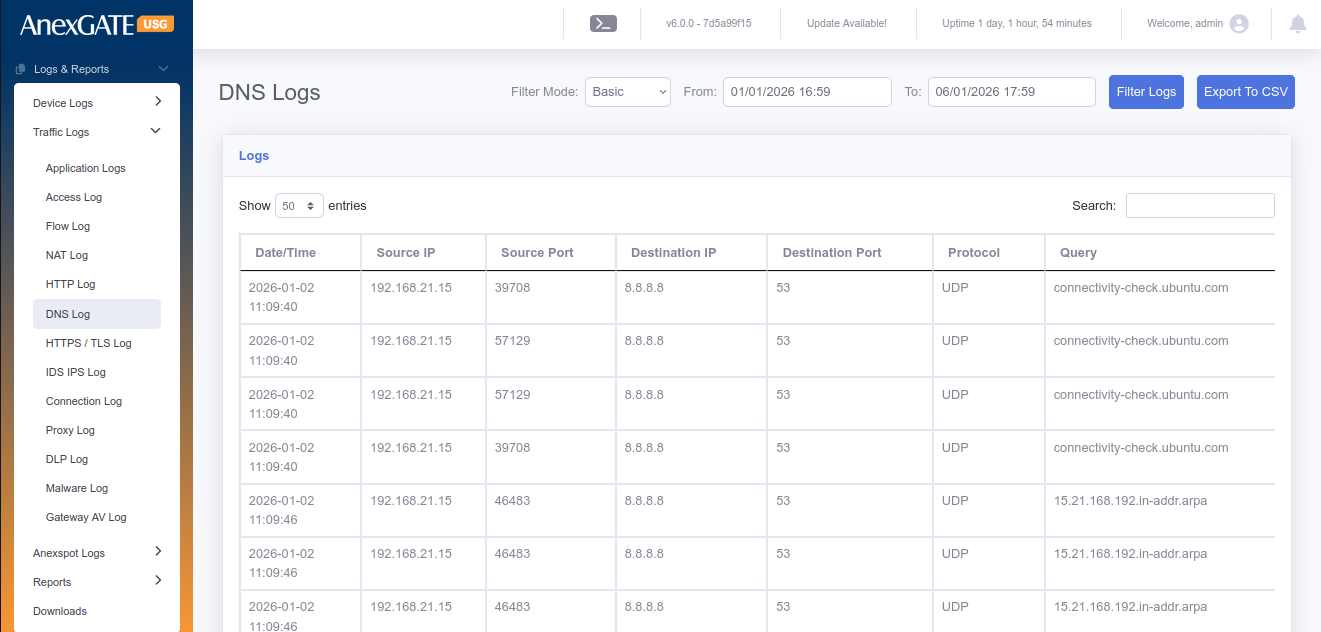
¶ 9.8 DNS LOG
DNS Logs display the event of time where the user DNS queries are resolved by the DNS IP along with the domain name of the destination.
To check the DNS Log, Go to Logs > DNS Log.
¶ 9.9 SSL LOG
SSL Logs display the event of the user access https websites. SSL Log will show the timestamp of the request made by the User IP and the response by the server.
To check the SSL Log Go to Logs > SSL Log.
¶ 9.10 FILES LOG
Files log displays the files downloaded by the users. The File names can be differentiated in terms of MIME Type.
To check the File Log Go to Logs > Files Log.
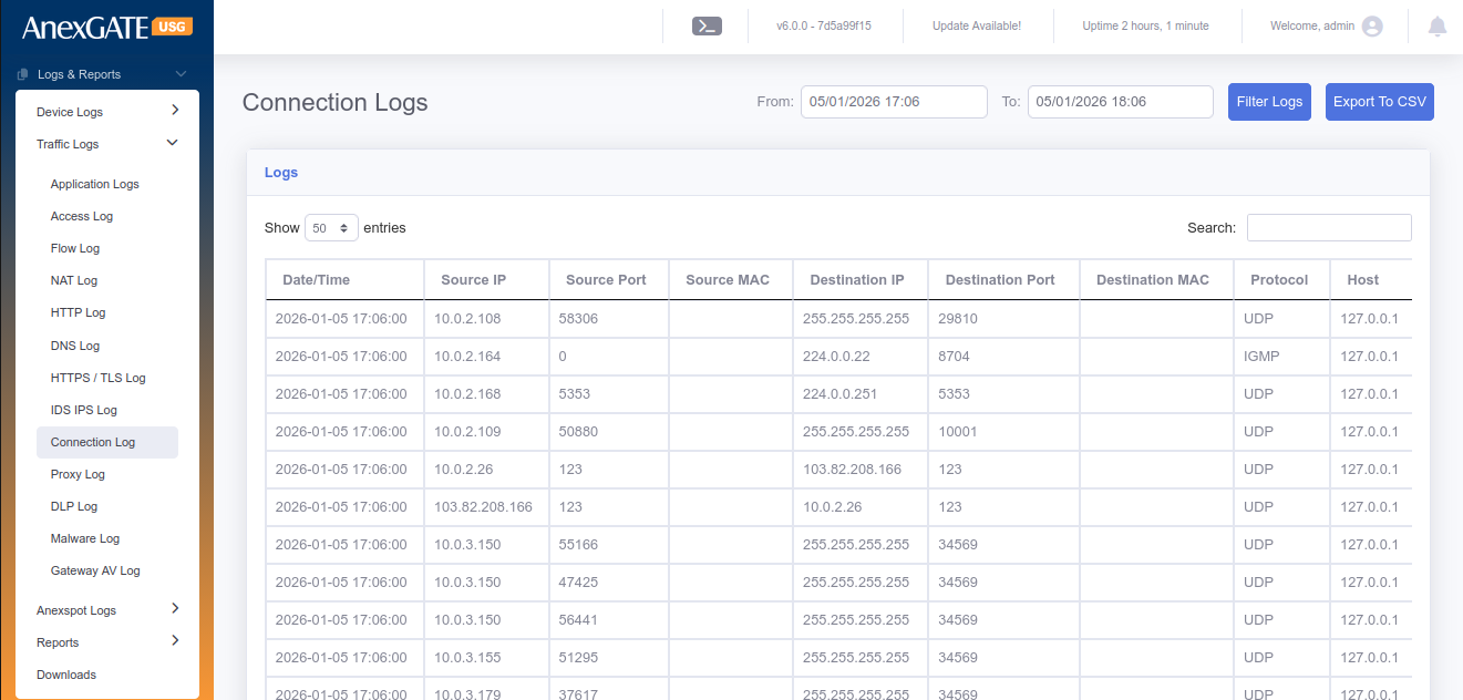
¶ 9.11 CONNECTION LOG
Connection Log displays the connection tracking of the traffic flow from source to destination.
To check the Connection Log Go to Logs > Connection Log.
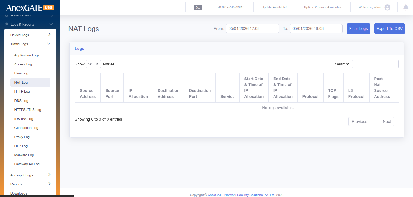
¶ 9.12 NAT TABLE
NAT Table displays the Local and Global IP being NAT’D from source when requests are being made as well as Destination NAT response from incoming traffic.
To check the NAT TABLE Log Go to Logs > NAT TABLE Log.
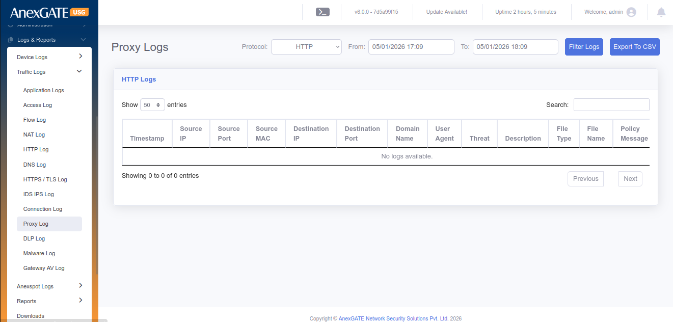
¶ 9.13 PROXY LOG
Proxy Log displays the event of accessing the webpage by the user when the HTTP/HTTPs Proxy has been enabled.
To check the proxy Log Go to Logs > Proxy Log.
¶ 10 USERS AND GROUPS
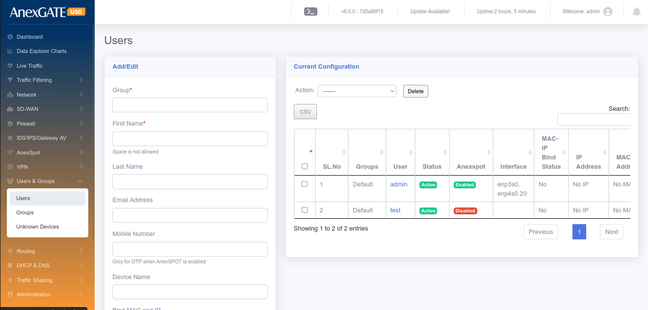
¶ 10.1 USERS
To configure Users, Go to Users & Groups > Users.
PARAMETERS
| ELEMENTS | DESCRIPTION |
|---|---|
| Group | Select Group where you want to add the User. |
| First Name* | Enter the First name of the user or endpoint device. |
| Last Name | Enter the last name of the user or endpoint device. (Optional) |
| Device | Enter Device name. (Optional) |
| Mobile Number | Enter Mobile Number (Optional) |
| Email Address | Enter Email Address (Optional) |
| Bind MAC and IP | Select YES to assign same IP Address everytime to MAC Address of the endpoint device. The DHCP Static Lease rule is created for the same. |
| DHCP Server | Select DHCP Server from the Dropdown list after selecting Bind MAC and IP. |
| MAC Address | Enter MAC Address of the Endpoint Device |
| IP Address | Enter IP Address of the Endpoint Device. |
| Username | Enter Username if AnexSPOT is enabled for authentication purpose. |
| Password | Enter Password if AnexSPOT is enabled for authentication purpose. |
| Is User Active? | Assign User Active state or Inactive state. If inactive, the AnexSPOT Policy wont work on the user. |
| Add to AnexSPOT whitelist | Select this for the AnexSPOT to be bypassed without asking for username or password for authentication |
| MAC Lookup Lock | Initial System MAC Address used to login through AnexSPOT login are saved. Only those devices are able to login via AnexSPOT later. |
| Login Expiry Date | Enter the Expiry date for Login Credentials (dd/mm/yyyy). |
| AnexSPOT Logins Allowed | Number of devices or logins allowed for AnexSPOT. |
| SAVE | Save the user configuration settings. |
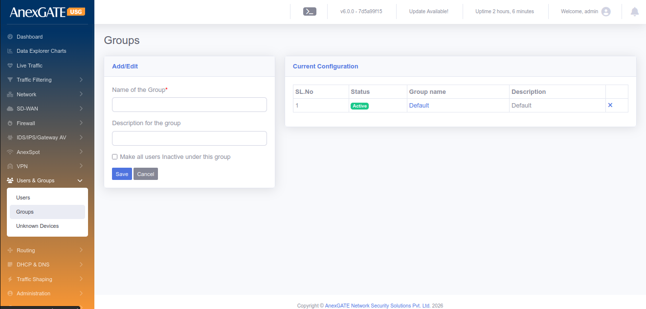
¶ 10.2 GROUPS
To configure groups, Go to Users & Groups > Groups.
PARAMETERS
| ELEMENTS | DESCRIPTION |
|---|---|
| Name of the Group* | Add a name to the Group where you want to add the users in. |
| Description | Add a description to the Group. |
| SAVE | Save the group configuration settings |
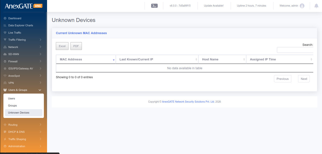
¶ 10.3 UNKNOWN DEVICES
To view the list of unknown devices connected, Go to Users & groups > Unknown Devices.
PARAMETERS
| ELEMENTS | DESCRIPTION |
| MAC Address | MAC Address will be shown of the non-user connected to USG |
| Last Known/Current IP | Last known or current IP will be displayed given to the non-user |
| Hostname | Device Hostname will be displayed if available |
| Assigned IP Time | IP assigned Time will be displayed. |
¶ 11. ROUTING
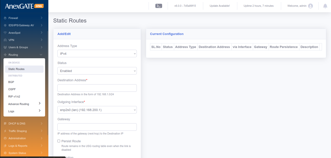
¶ 11.1 STATIC ROUTES
To configure Static Routes, Go to Routing > Static Routes.
¶ PARAMETERS
| ELEMENTS | DESCRIPTION |
|---|---|
| Status | Enable or Disable the Static route configuration |
| Destination Address | Specify Destination Address (Example – 192.168.0.0/24) and is Required. |
| Outgoing Interface | Specify Outgoing Interface from the list. Default route is used if no interface is specified and interface is required to define the route. |
| Gateway | Specify the Next-Hop Gateway IP towards the Destination IP and is required. |
| Persist Route | Select this optional field for the route to remain in the USG routing table even when the link is down or disabled. |
| Description | Description of the Static Route Configuration. |
| SAVE | Save the Static Route configuration settings. |
NOTE: To edit the existing routes, Click on the Sl No. From the Current Configuration and change.
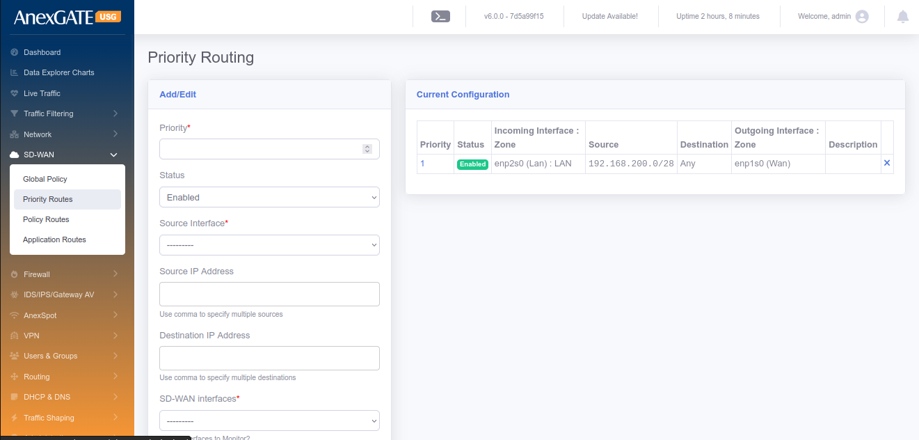
¶ 11.2 PRIORITY ROUTES
To configure Priority Routes, Go to Routing > Priority Routes.
NOTE: These routes are effective only when the multiple WAN interfaces are configured and Multiwan is enabled.
¶ PARAMETERS
| ELEMENTS | DESCRIPTION |
|---|---|
| Priority* | Priority of the route to be added and is required. |
| Status | Enable or Disable the Priority Route Configuration |
| Incoming Interface* | Select Incoming Interface from the list |
| Source IP Address | Specify Source IP address optional and If no specific IP/subnet then whole lan network is considered. |
| Destination IP Address | Specify the optional Destination IP address or leave blank for any destination. |
| Outgoing Interface | Select Outgoing Interface from the list. |
| Sticky Route | Click on Sticky router to not remove the route even when the outgoing interface goes down. |
| Description | Add a description to the Priority Route rule |
| SAVE | Save the priority route rule configuration settings |
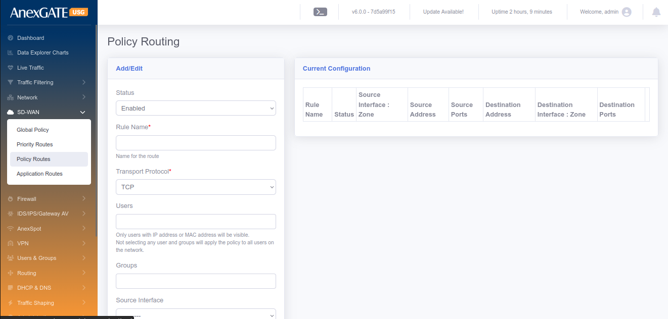
¶ 11.3 POLICY ROUTES
To configure Policy Routes, Go to Routing > Policy Routes.
NOTE: These routes are effective only when the multiple WAN interfaces are configured and Multiwan is enabled.
¶ PARAMETERS
| ELEMENTS | DESCRIPTION |
|---|---|
| Status | Enable or Disable the Policy Route configuration |
| Rule Name | Add a name to the policy route rule |
| Source Address | Specify Source Address for the policy route |
| Exclude Source Address | Specify Source IPs from the source network address to be excluded from the policy route. (Use comma to specify multiple addresses as such 192.168.0.10,192.168.0.11) |
| Source Ports | Specify Source ports (Use comma to specify multiple ports as such 80,443,8080) |
| Source Interface | Select Source Interface for the policy route |
| Destination Address | Specify Destination Address for the policy route |
| Exclude Destination Address | Specify Destination IPs from the destination network address to be excluded from the policy route. (Use comma to specify multiple addresses as such 192.168.0.10,192.168.0.11) |
| Destination Ports | Specify Destination ports (Use comma to specify multiple ports as such 80,443,8080) |
| Destination Route | Select Destination Interface for the policy route |
| Transport Protocol | Select the Transport protocol for the policy route (TCP, UDP or ALL) |
| SAVE | Save the Policy route configuration settings |
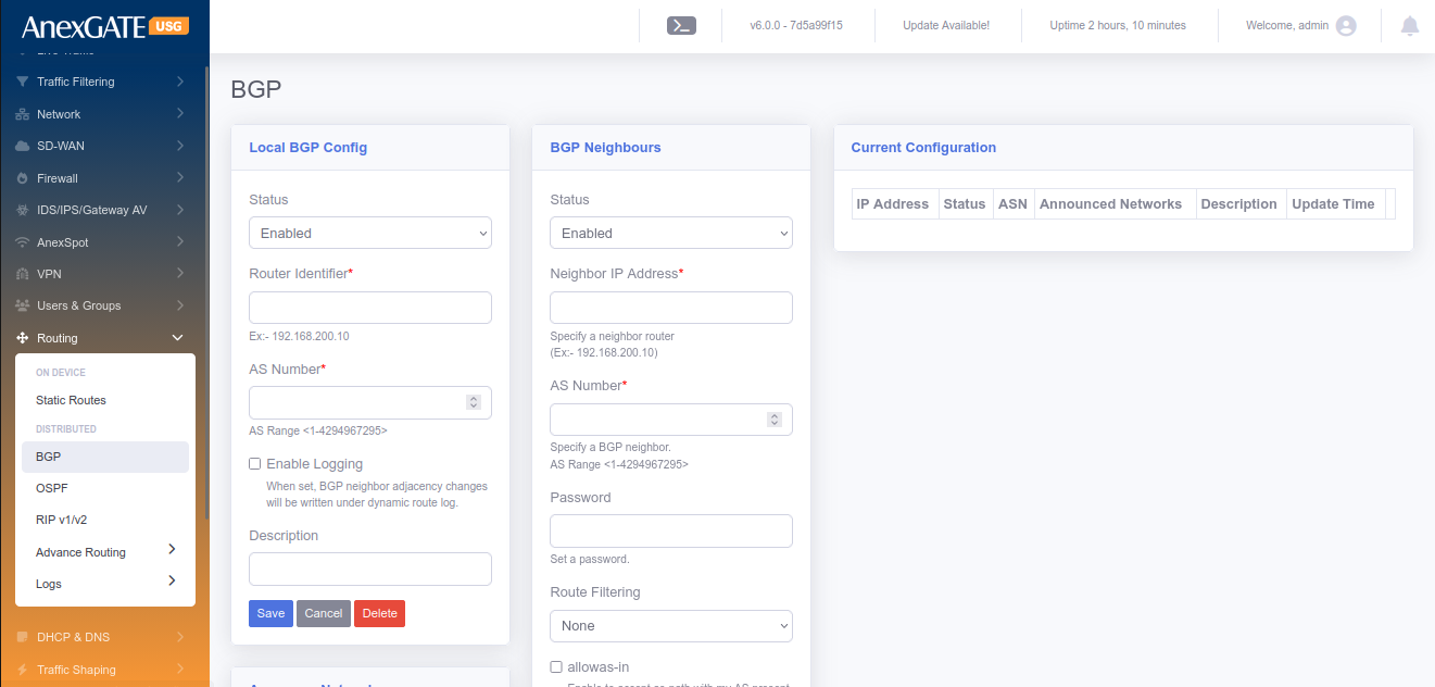
¶ 11.4 BGP
To configure BGP Routing, user should enable the BGP protocol in the Routing > Options and select BGP.
PARAMETERS
| ELEMENTS | DESCRIPTION |
|---|---|
| Status | Enable or Disable the BGP Routing Configuration |
| Router Identifier | Identifier of the Router |
| AS Number | AS number of BGP routes |
| Description | Add a description to the BGP Route. |
| SAVE | Save the BGP rule configuration settings |
PARAMETERS (BGP Neighbours)
| ELEMENTS | DESCRIPTION |
|---|---|
| Status | Enable or Disable the BGP Routing Configuration |
| Neighbour IP Address | IP Address of the Neighbour BGP Router. |
| Priority | Priority for the routes of the BGP |
| AS Number | Remote side AS number of the BGP |
| Announce Networks | Single network or comma separated multiple IP/Subnets to announce the networks over BGP. |
| Description | Add a description to the BGP Route. |
| SAVE | Save the BGP rule configuration settings |
¶ 11.5 OSPF
To configure OSPF Routing, user should enable the OSPF protocol in Routing > Options and select OSPF.
PARAMETERS
| ELEMENTS | DESCRIPTION |
|---|---|
| Status | Enable or Disable the OSPF Routing Configuration |
| Router Identifier | Required router identifier might be a IP address |
| Default Metric | Default metric of the OSPF routes. |
| ABR Type | Select ABR type of the selection. Available options are “Cisco”, “IBM”, “Shortcut” and “Standard”. |
| Auto Cost Ref. Bandwidth (Mbps) | Provide the Cost reference bandwidth in Mbps and is required. |
| Default Information Originate | Select proper selection and available options are “never”, “Regular and “Always”. |
| Redistribute Connected | Select/Deselect Redistribute of the connected. |
| Redistribute Connected Metric | Provide proper metric value for connected Redistribute. |
| Redistribute Connected Metric Type | Select Metric type as “Type1” or “Type2”. |
| Redistribute Static | Select/Deselect Redistribute Static. |
| Redistribute Static Metric | Provide proper metric value for Static Redistribute. |
| Redistribute Static Metric Type | Select Metric type as “Type1” or “Type2” |
| Redistribute RIP | Select/Deselect Redistribute RIP. |
| Redistribute RIP Metric | Provide proper metric value for RIP Redistribute. |
| Redistribute RIP Metric Type | Select Metric type as “Type1” or “Type2”. |
| Redistribute BGP | Select/Deselect Redistribute BGP. |
| Redistribute BGP Metric | Provide proper metric value for BGP Redistribute. |
| Redistribute BGP Metric Type | Select Metric type as “Type1” or “Type2” |
| SAVE | Save the OSPF rule configuration settings. |
After configuring the above global OSPF configuratiuons, User may need to configure Interfaces, Areas and Networks.
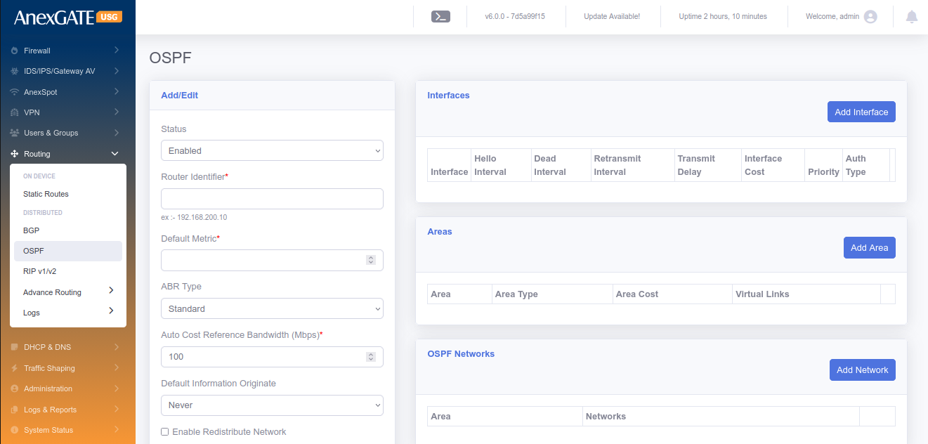
¶ 11.5.1 INTERFACES
To add the OSPF interfaces for the current OSPF configurations.
PARAMETERS
| ELEMENTS | DESCRIPTION |
|---|---|
| Interface | Select the interface from the available list of interfaces. |
| Hello Interval | Hello interval in Secs. |
| Dead Interval | Dead Interval in Secs. |
| Retransmit Interval | Retransmit Interval in Secs. |
| Transmission Delay | Delay in Secs. |
| Interface Cost | Cost to the interface for the OSPF routing. |
| Priority | Priority used for the this routes over OSPF. |
| Auth Type | Select the Auth type from the list and available types are “None”, “Text” and “MD5”. |
| MD5 Key ID | MD5 Key ID if Auth type selected as MD5. |
| Passkey | Password to establish the OSPF route exchange. |
| SAVE | Save the OSPF Interface configuration settings. |
¶ 11.5.2 AREAS
To configure Areas are used in the OSPF are as follows.
PARAMETERS
| ELEMENTS | DESCRIPTION |
|---|---|
| Area | Area for the OSPF. Normally 0.0.0.0 is used. |
| Area Type | Select the Type of the Area and available types are “None”, “Normal”, “Stub”, “Stub No-summary” “NSSA” and “NSSA No-Summary”. |
| Area Cost | Cost of the Area. |
| Virtual Links | Single or comma separated multiple links for OSPF Area links. |
| SAVE | Save the OSPF Area configuration settings. |
¶ 11.5.3 NETWORKS
To configure Networks to be broadcasted over OSPF are as follows.
PARAMETERS
| ELEMENTS | DESCRIPTION |
|---|---|
| Area | Area for the OSPF. Normally 0.0.0.0 is used. |
| Networks | Enter IP/Subnet or comma separated multiple IP/Subnets combinations. |
| SAVE | Save the OSPF Networks configuration settings. |
NOTE: Any configurations can be edited by clicking the specific current configurations and resave the configurations.
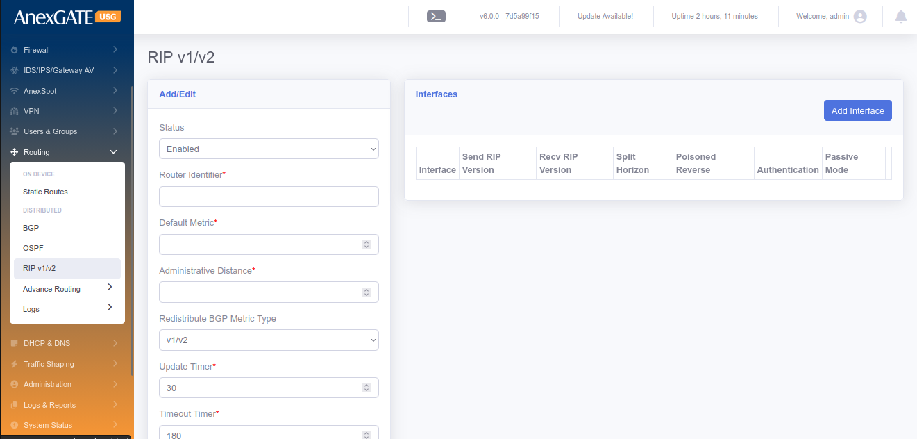
¶ 11.6 RIP v1/v2
To configure RIP v1/v2 Routing, first user may need to enable RIP, should enable the RIP protocol in the Routing > Options and select RIP.
PARAMETERS
| ELEMENTS | DESCRIPTION |
|---|---|
| Status | Enable or Disable the OSPF Routing Configuration. |
| Router Identifier | Required router identifier might be a IP address. |
| Default Metric | Default metric used for the RIP. |
| Administrative Distance | Provide the numeric value for Administrative Distance. |
| Redistribute BGP Metric Type | Select from the drop-down list and the available options are “v1/v2”, “v1” and “v2” |
| Update Timer | Update timer in Secs. |
| Timeout Timer | Timeout timer in Secs. |
| Garbage Timer | Garbage timer in Secs. |
| Default Information Originate | Select/Deselect the originate information use default. |
| Redistribute Connected | Select/Deselect Redistribute Connected. |
| Redistribute Connected Metric | Provide proper metric value for Connected Redistribute. |
| Redistribute Static | Select/Deselect Static Redistribute. |
| Redistribute Static Metric | Provide proper metric value for Static Redistribute. |
| Redistribute RIP | Select/Deselect the Redistribute RIP Option. |
| Redistribute RIP Metric | Provide proper metric value for RIP Redistribute. |
| Redistribute BGP | Select/Deselect Redistribute BGP option. |
| Redistribute BGP Metric | Provide proper metric value for BGP Redistribute. |
| Networks | Provide the networks in IP/Subnet or comma separated multiple IP/Subnets. |
| SAVE | Save the RIP configuration settings. |
¶ 11.7 OPTIONS
To enable the protocols to be enabled on the AnexGATE USG.
PARAMETERS
| ELEMENTS | DESCRIPTION |
|---|---|
| BGP | Select to enable BGP Protocol. |
| OSPF | Select to enable OSPF Protocol. |
| IS-IS | Select to enable IS-IS Protocol. |
| RIP | Select to enable RIP Protocol. |
| RIPng | Select to enable RIPng Protocol. |
| Routing Console Terminal | Select to enable Console Terminal Protocol. |
| SAVE | Save the Options configuration settings. |
¶ 12. DHCP & DNS
¶ 12.1 DHCP SERVER
To configure DHCP Server, Go to DHCP & DNS > DHCP Server.
¶ PARAMETERS
| ELEMENTS | DESCRIPTION |
|---|---|
| Status | Enable or Disable the DHCP Server. |
| DHCP Interface* | Select DHCP Interface for LAN port configured to assign IP address. |
| Start IP Address* | Enter the start range of the LAN IP Address configured. |
| End IP Address* | Enter the end range of the LAN IP Address configured. |
| Primary DNS* | Assign Primary DNS server IP. |
| Secondary DNS* | Assign Secondary DNS server IP. |
| NTP Server | Assign NTP server to LAN (optional). |
| Lease Duration | Assign DHCP Lease duration in seconds. Default = 7200. |
| Maximum Lease Duration | Assign Maximum Lease Duration in seconds. Default = 84000. |
| Search Domain | Assign a domain name to be resolved by LAN Gateway IP. |
| Lan Isolation | Click on LAN Isolation if the request/response should go through Firewall first to prohibit LAN users to communicate with each other directly. |
| Enable NetBIOS | Click on NetBIOS to enable WINS for Windows Systems. A WINS server maps computer NetBIOS names to IP Address. |
| Disallow DHCP for unknown clients | Click on Disallow DHCP for unknown clients to not assign an IP address to a client that does not have a MAC Binding defined in Users under Users & Groups. |
| SAVE | Save the DHCP Server Configuration settings. |

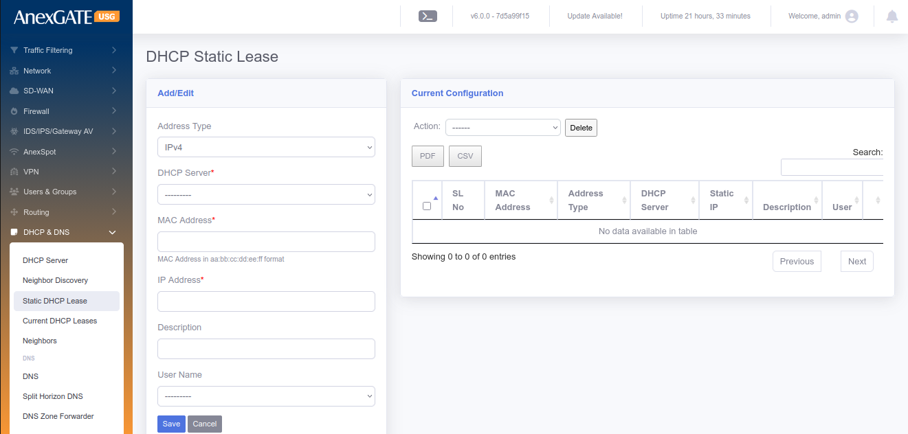
¶ 12.2 STATIC DHCP LEASE
To configure Static DHCP Lease, Go to DHCP & DNS > Static DHCP Lease.
¶ PARAMETERS
| ELEMENTS | DESCRIPTION |
|---|---|
| DHCP Server* | Select the LAN Interface of configured DHCP Server. |
| MAC Address* |
Enter MAC Address in aa:bb:cc:dd:ee:ff format Example - 08:dc:98:7f:8c:d4 |
| IP Address* | Select IP Address of the System or any endpoint connected to LAN. |
| Description | Add a Description for the configuration. |
| User Name | Select a Username from the dropdown list if any created in Users & Groups (optional). |
| Import User MAC & IP | Download the CSV template, Edit it and upload multiple MAC & IP Address at once for DHCP Static Lease configuration. |
| SAVE | Save the Static DHCP Lease configuration settings. |
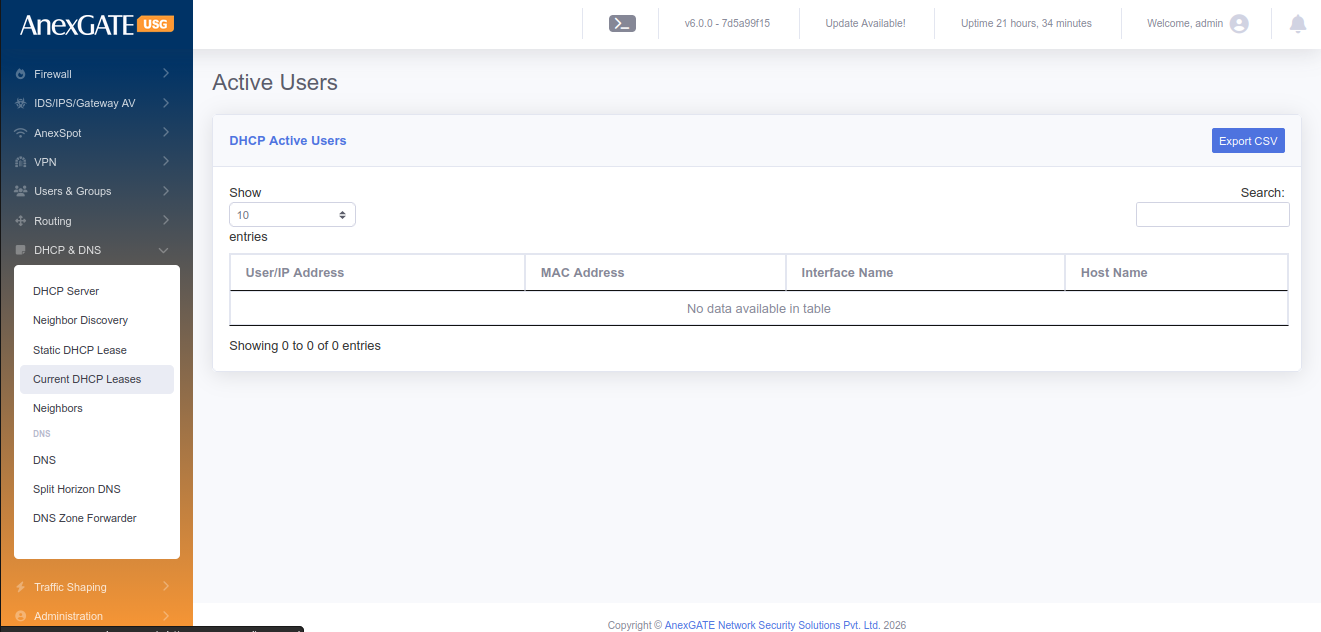
¶ 12.3 CURRENT DHCP LEASES
To view current DHCP Leases, Go to DHCP & DNS > Current DHCP Leases.
¶ PARAMETERS
| ELEMENTS | DESCRIPTION |
|---|---|
| USER/IP Address | Displays User name if configured or the IP Address of the Endpoint. |
| MAC Address | Displays MAC Address of the Endpoint |
| Interface Name | Displays the LAN Interface |
| HostName | Displays the HostName of the system Endpoint if any. |
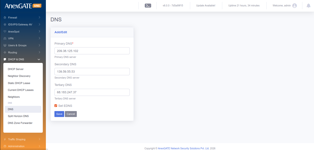
¶ 12.4 DNS
To configure DNS, Go to DHCP & DNS > DNS.
¶ PARAMETERS
| Primary DNS | Assign Primary DNS Server IP |
| Secondary DNS | Assign Secondary DNS Server IP |
| Tertiary DNS | Assign Tertiary DNS Server IP |
| SAVE | Save the DNS configuration settings |
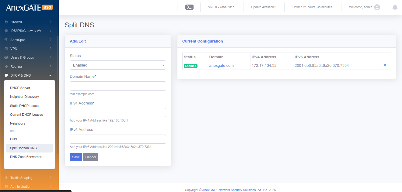
¶ 12.5 SPLIT HORIZON DNS
Split Horizon DNS enables the user to redirect the DNS queries to local machine instead of going on public IP if the DNS Server is configured USG Firewall LAN Gateway.
To configure Split Horizon DNS, Go to DHCP & DNS > Split Horizon DNS.
¶ PARAMETERS
| ELEMENTS | DESCRIPTION |
|---|---|
| Status | Enable or Disable the Split Horizon DNS configuration |
| Domain Name* | Enter the Domain Name to be resolved |
| IP Address | Enter the Local LAN IP Address of the endpoint device |
| SAVE | Save the Split DNS configuration settings. |
¶ 13. QOS
¶ 13.1 USER QOS
To configure User QoS, Go to QoS > User QoS.
PARAMETERS
| ELEMENTS | DESCRIPTION |
|---|---|
| Status | Enable or Disable the QoS status for User. |
| QOS for Subnet |
Click this and Enter the subnet for which the QoS rule is to be enforced Subnet – Enter a subnet to apply QoS QOS per IP – Click this to apply the QOS for each host as opposed to the entire Subnet. This means, the QoS will be applied on each host instead of whole subnet |
| User | Choose user from the list to apply QoS. |
| Bandwidth Unit | Select the Bandwidth unit in Mbps or Kbps |
| Upload Bandwidth Rate | Enter the Upload Bandwidth Rate to be alloted to the User or Subnet |
| Download Bandwidth Rate | Enter the Download Bandwidth Rate to be alloted to the User or Subnet |
| SAVE | Save the User QoS configuration settings. |
¶ 13.2 GROUP QOS
To configure Group QoS, Go to QoS > Group QoS.
PARAMETERS
| ELEMENTS | DESCRIPTION |
|---|---|
| Status | Enable or Disable the QoS status for Group |
| Group | Choose group from the list to apply QoS. |
| Bandwidth Unit | Select the Bandwidth unit in Mbps or Kbps |
| Upload Bandwidth Rate | Enter the Upload Bandwidth Rate to be alloted to the User or Subnet |
| Download Bandwidth Rate | Enter the Download Bandwidth Rate to be alloted to the User or Subnet |
| SAVE | Save the Group QoS configuration settings. |
¶ 13.3 APPLICATION QOS
To configure Application QoS, Go to QoS > Application QoS.
PARAMETERS
| ELEMENTS | DESCRIPTION |
|---|---|
| Status | Enable or Disable the QoS status for Applications |
| Applications | Select Applications from the list to apply QoS |
| Users | Choose user from the list to apply QoS. |
| Groups | Choose group from the list to apply QoS. |
| Upload Bandwidth Rate | Enter the Upload Bandwidth Rate to be alloted to the User or Subnet |
| Download Bandwidth Rate | Enter the Download Bandwidth Rate to be alloted to the User or Subnet |
| Bandwidth Unit | Select the Bandwidth unit in Mbps or Kbps |
| SAVE | Save the Application QoS configuration settings. |
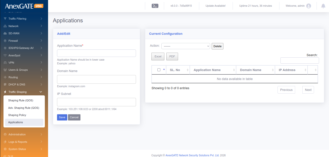
¶ 13.4 DEFINE APPLICATION
To configure or add Applications manually to apply Application QoS,
Go to QoS > Define Application.
PARAMETERS
| ELEMENTS | DESCRIPTION |
|---|---|
| Application Name | Enter a name for the Application QoS |
| Protocol | Select protocol TCP / UDP / ALL ( both TCP & UDP) |
| Port Numbers | Enter port number for the Application for QoS |
| SAVE | Save the Application settings. Use this to configure Application QoS |
¶ 14. FIREWALL
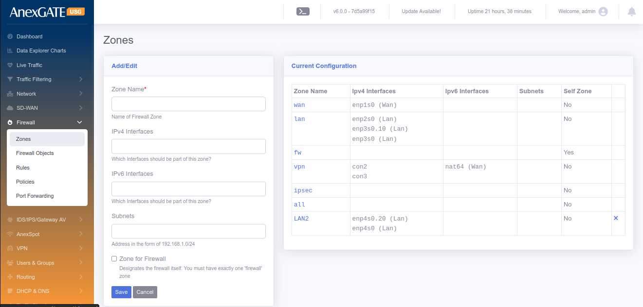
¶ 14.1 ZONES
To configure Firewall Zones, Go to Firewall > Zones.
¶ PARAMETERS
| ELEMENTS | DESCRIPTION |
|---|---|
| Zone Name | Enter name of the zone for the interfaces you want to assign |
| Interfaces | Select the physical interfaces (WAN-enp1s0, LAN-enp2s0 etc..) |
| Subnets | Enter the network suubnet of the interface if required to specify. (Example: 192.168.100.0/24) |
| Zone for Firewall | Select this if the Zone is to be made for Firewall. |
| Allow AnexSPOT | Allows AnexSPOT to work for the Zone. |
| SAVE | Save the settings to configure the Zone. |
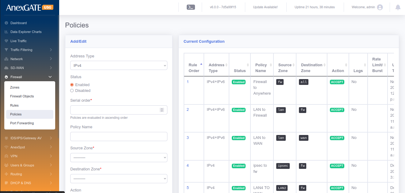
¶ 14.2 POLICY
To configure Firewall Policy, Go to Firewall > Policy.
¶ PARAMETERS
| ELEMENTS | DESCRIPTION |
|---|---|
| Status | Enable or Disable the policy. |
| Serial Order | Enter a serial number to categorise policies |
| Policy Name | Enter the name of the Firewall Policy |
| Source Zone | Select the zone from the dropdown list configured in Firewall > Zones as the Source Zone |
| Destination Zone | Select the zone from the dropdown list configured in Firewall > Zones as the Destination Zone |
| Action |
ACCEPT – Select this to allow communication between Zones DROP – Select this to drop communication between Zones REJECT – Select this to drop as well as send a TCP-RST packet to the sender. |
| Enable Logging | Select this to get logs generated by the Firewall Policy. |
| SAVE | Save the configuration settings of the Firewall policy. |
NOTE: By default, there are 4 policy configured (rule1, 2, 3 and 1000). These rules cannot be deleted but can be enabled or disabled. There is an arrow key at the information table which can be used to ascend or descend the policy.
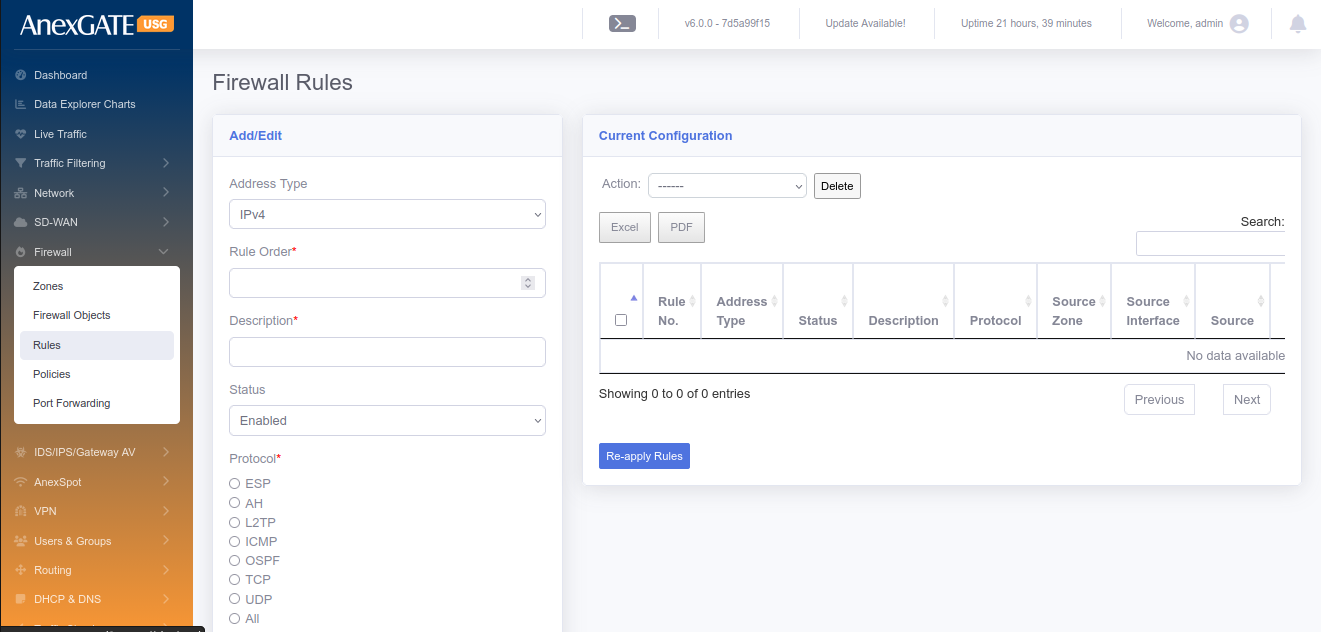
¶ 14.3 RULES
To configure Firewall Rules, Go to Firewall > Rules.
¶ PARAMETERS
| ELEMENTS | DESCRIPTION |
|---|---|
| Rule Order | Enter Rule Order in terms of numerical order. |
| Description | Add a description to the Firewall rule |
| Status | Enable or Disable status of the Firewall rule |
| Protocol | Select Network Protocol (TCP, UDP, ICMP etc..) to allow or drop traffic |
| Service | Select Services from Dropdown list to apply the firewall rule. |
| Source Countries | Select Source country for the firewall rule to allow or drop traffic |
| Source Zone | Select Source Zone from dropdown list to which the rule applies. |
| Source Interface | Select Source Interface if there are multiple interfaces and need only a single interface to which the rule applies |
| Source | Enter Souce IP or MAC of the host to which the rule applies. |
| Source Port | Enter Source Port of the host to which the rule applies. |
| Destination Countries | Select Destination Countries for the firewall rule to allow or drop traffic |
| Destination Zone | Select Destination Zone from dropdown list to which the rule applies. |
| Destination Interface | Select Destination Interface if there are multiple interfaces and need only a single interface to which the rule applies. |
| Destnation | Enter Destination of the host to which the rule gets applied. |
| Destination Port | Enter Destination Port of the host to which the rule gets applied. |
| What to do? |
Options to choose from: Accept – Allows access Drop – Discards access Reject – Denies Access and ICMP Port Unreachable will be sent to the source |
| Time Based Rule | Enable or Disable to schedule the rule. |
| From/To Date | Enter From/To Date for the rule to be applied. |
| From/To Time | Enter From/To Time for the rule to be applied. |
| Days of Week | Select Days in a week for the rule to be applied. |
| Days of Month | Select Days of month for the rule to be applied. |
| AnexSPOT Bypass | Click to Bypass AnexSPOT restriction for rule. |
| Proxy Bypass | Click to Bypass Proxy if proxy server is enabled. |
| Enable Logging | Click to enable traffic logging for the rule i.e, traffic allowed or dropped by the Firewall rule. |
| Keywords | Assign a keyword to comply it to a firewall rule. |
| SAVE | Save the configuration settings of the Firewall rule. |
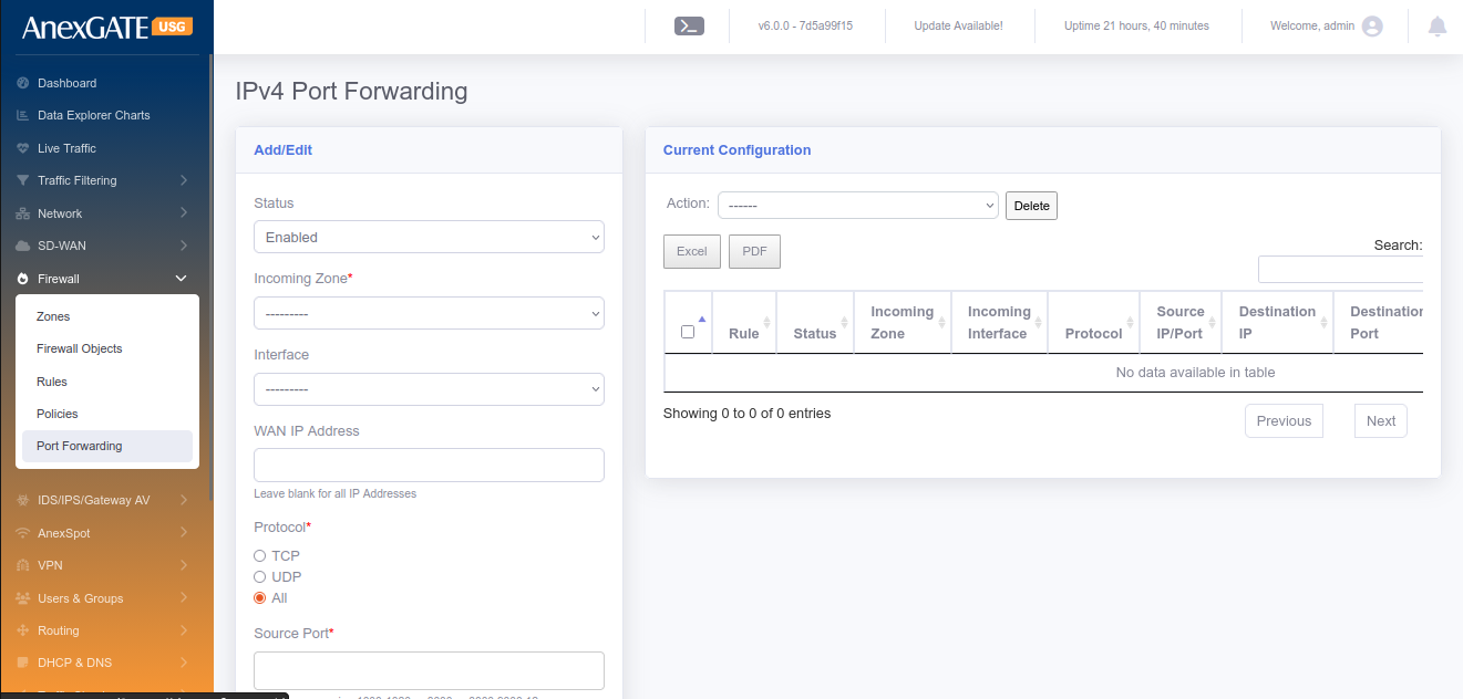
¶ 14.4 PORT FORWARDING
To configure Port Forwarding, Go to Firewall > Port Forwarding.
¶ PARAMETERS
| ELEMENTS | DESCRIPTION |
|---|---|
| Status | Enable or Disable the Port Forwarding rule. |
| Incoming Zone* | Select WAN as Incoming Zone. (To do Hair Pin NAT, select LAN as Incoming Zone) |
| Incoming Interface |
Select WAN interface if there are multiple interface. Leaving this parameter blank will be considered as to include all WAN interfaces configured. |
| WAN IP Address | Specify WAN IP Address for Port Forwarding if there no interface selected. |
| Protocol | Select Transport Layer Protocol TCP/UDP or ALL protocols to be allowed. |
| Source Port | Specify Port Number for TCP/UDP protocol (0-65535). |
| Source IP Address | Enter Source IP Address to be Port Forwarded from. |
| Destination Zone* | Select LAN Zone. |
| Destination IP Address | Select LAN IP for port forwarding |
| Destination Port | Specify Specific Port Number to listen on. |
| Service | Select the service from the list. (Example: FTP, PPTP, SNMP, TFTP) |
| Hair Pin NAT | Select this option to allow the internal network hosts to reach the port forwarded services using the public IP, locally. |
| Enable Logging | Click to enable traffic logging for the rule i.e, traffic allowed or dropped. Logs can be seen at, Logs > Traffic Logs > NAT Table |
| Description | Add a description to the Port Forwarding rule. |
| SAVE | Save the configuration settings of the Port Forwarding rule. |
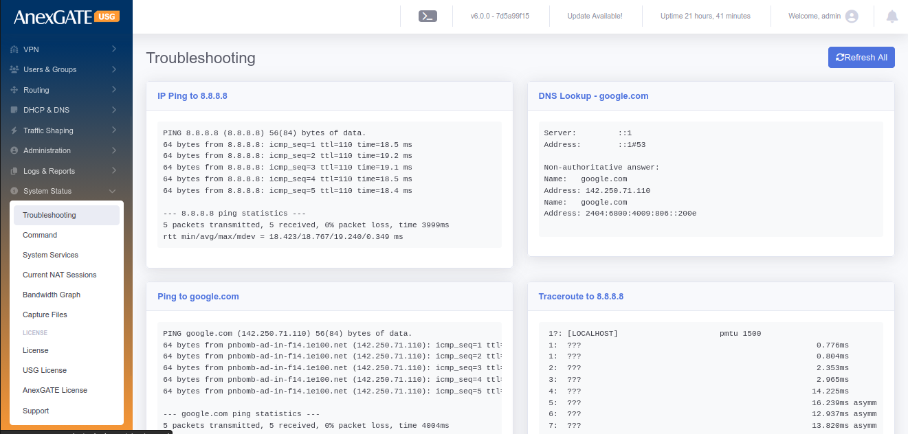
¶ 15. ADMIN
¶ 15.1 TROUBLESHOOTING
Go to Admin > Troubleshooting. Click on the Troubleshooting tab to execute a set of networking commands all at once and display the output such as follows:
| COMMAND | DESCRIPTION |
|---|---|
| Ping IP | Pings IP 8.8.8.8 and checks the reachability |
| DNS Lookup | Checks DNS resolve for google.com |
| Ping Domain | Pings google.com and checks the reachability |
| Traceroute IP | Traceroutes 8.8.8.8 and checks the reachability through hops |
| IP Route | Displays IP Route Table along with Default route, Failover Table as well as IPSec table |
| Current IP | Displays the current Public IP of the connection. |
¶ 15.2 COMMANDS
Go to Admin > Command, to run or execute commands to diagnose and troubleshoot Network problems in AnexGATE USG Firewall. Below are the list of commands which are included as follows:
| COMMAND | ARGUMENT | DESCRIPTION |
|---|---|---|
| ping | <domain / ip address> |
Checks the reachability to the Domain or IP.
|
|
<domain / ip address> -I <interface>
|
Checks the reachability to the Domain or IP address on a particular interface. **<interface> = enp1s0,enp2s0 etc.. |
|
| -I <src. ip address> <dest. domain / ip address> | Checks the reachability from source Domain or IP address to the destination Domain or IP address. | |
| ifconfig | **no argument** |
Displays ‘active’ interface configuration.
|
| -a | Displays interface configuration along with ‘inactive’ interfaces. | |
| <interface> | Displays only interface configuration. | |
| lsusb | **no argument** | Displays information about USB buses in the system and the devices connected to them. |
| traceroute | <domain / ip address> | Displays the route that a packet takes to reach the host. Useful, when you want to know about the route and about all the hops that a packet takes. |
| -n <domain / ip address> | Do not resolve IP addresses of hops to their domain names while traceroute. | |
| dnslookup | <domain / ip address> | Displays “A Record” (IP Address) of the domain and vice-versa. Use this command to find the address record for a domain. It queries to domain name servers and get the details. |
| iproute | **no argument** | Displays IP/kernel routing table, MultiWAN Failover table, IPSec Table. |
| ipsec status | **no argument** | Displays in-detail verbose output the IPSec Tunnel status. |
| ipsec policy | **no argument** |
Displays IP xfrm policy of IPSec Tunnel.
|
| speedtest | **no argument** |
Runs speedtest on active wan connection.
|
| --list | Displays number of server list to speedtest. | |
| --server <id no. from list> | Displays speedtest done on that particular server. | |
|
nmap
nmap |
<domain / ip address> |
Scans and displays open / filtered ports.
|
| -Pn <domain / ip address> | Treat all hosts as online and scans the ports. | |
| <domain / ip address> -p <port no.> | Display tcp port to be open / closed / filtered. *(Add , after port number to add add and scan multiple ports). | |
| -sU <domain / ip address> -p <port no.> | Display udp port to be open / closed / filtered. | |
| arp | **no argument** | Displays entries of resolved IP to MAC Address. |
| -n | Displays numerical addresses instead of symbolic host, port or usernames. | |
| route lookups | **no argument** |
Displays IP route lookup table with ID.
|
| Current ISP | **no argument** |
Displays current active WAN IP address.
|
| Network link status | <interface> | Displays verbose information of the port interface. |
| Firewall Rules | **no argument** | Displays Inbound and Outbound data Filter traffic rules with packets. |
| -t nat | Displays Inbound and Outbound NAT traffic rules with packets. | |
| -t mangle | Displays Inbound and Outbound Policy Route traffic rules with packets. | |
| HA Status | **no argument** | Displays the service and state / mode of the HA device. Master or Backup. |
| Netstat | -tulnp | Displays the ports listening on TCP and UDP. |
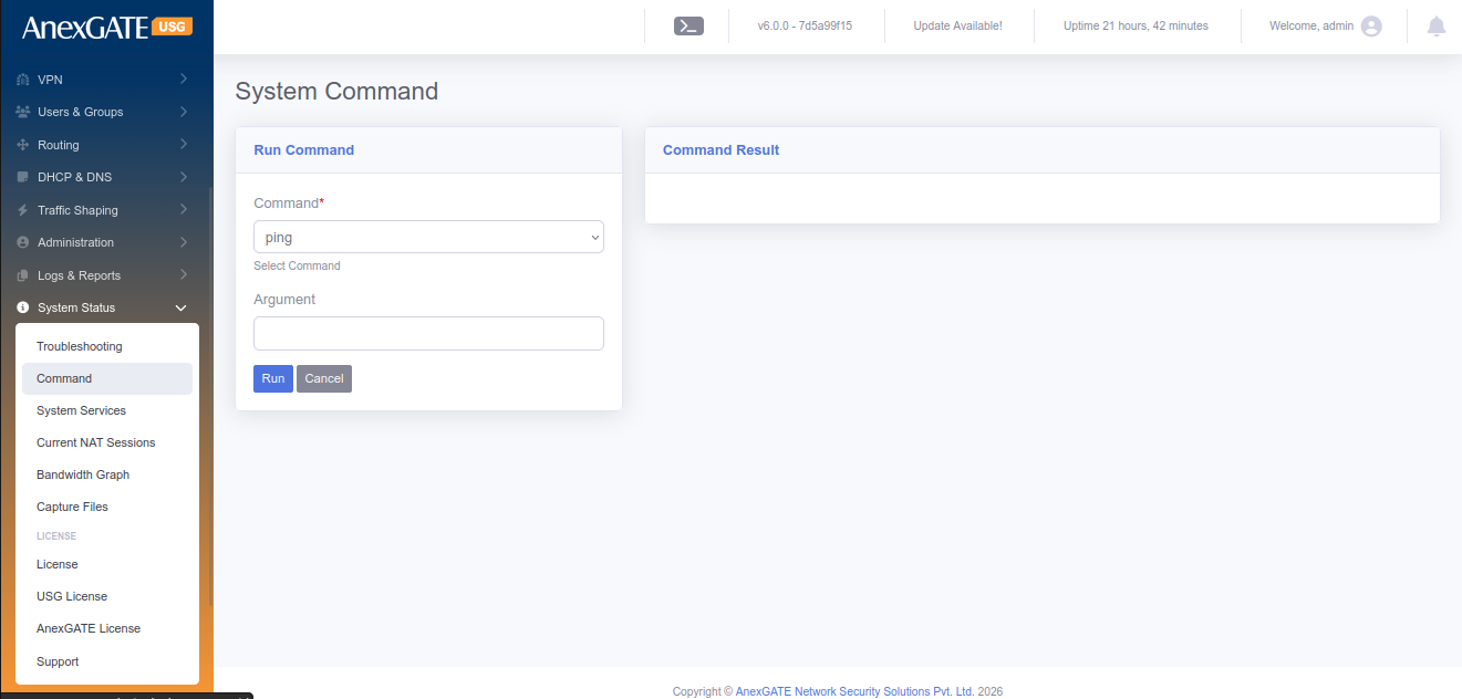
¶ 15.3 AUDIT LOG
Audit Log will log the event and displays if any changes are made in the Firewall configuration by any user or Admin.
Go to Admin > Audit Log to view the logs of any system or configuration changes. Audit will display the changes made as follows:
| ELEMENTS | DESCRIPTION |
|---|---|
| User | Displays the username of the user who accessed the firewall and changed the configuration |
| Timestamp | Displays the timestamp when the event occured in terms of Date/Time. |
| IP Address | Displays the IP Address of the system through which the event occured |
| Module |
Displays the Module name of the sections in the Firewall. Example: Admin login will trigger Admin Module Addition, Deletion or any changes made in Firewall policies or rules will trigger Firewall Module |
| Message | Displays Message for the type of event occured |

¶ 15.4 BANDWIDTH GRAPH
Bandwidth Graph will display the statistics of Incoming and Outgoing of traffic in terms of Kilo bit per second (Kbps) from the configured LAN/WAN Interfaces.
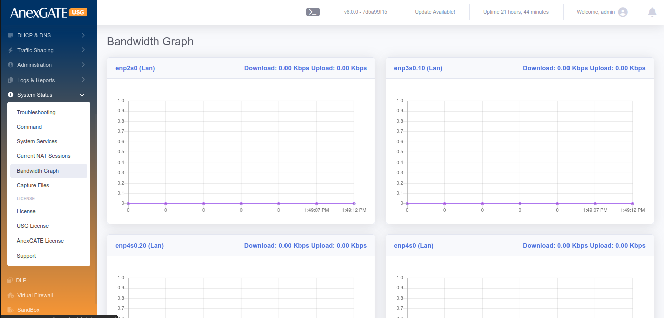
¶ 15.5 ADMIN LOGINS
To configure Admin Login credentials for Firewall, Go to Admin > Admin Logins.
PARAMETERS
| ELEMENTS | DESCRIPTION |
|---|---|
| First name | Enter a first name for the login user |
| Last name | Enter a last name for the login user (optional) |
| Email Address | Enter Email Address of the login user (optional) |
| Username* | Enter Username for the login user |
| Password* | Enter Password for the login user |
| Confirm Password* | Confirm the entered Password for the login user |
| Show Password | Click this for visibility when typing password |
| Active | Click this to designate the login user to be considered active NOTE: Inactive login users are not permitted to login to Firewall |
| Role* | Select the Role as Admin or Manager/Operator |
| API Access | Generate a API Token key to send requests to the USG |
| SAVE | Save the login user credentials. |
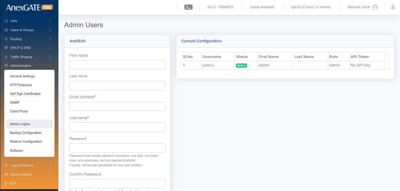
¶ 15.6 BACKUP CONFIGURATION
Go to Admin > Backup Configuration, for Backup Configuration file, of the AnexGATE USG Firewall can be downloaded manually or can be set to download the configuration automatically and sent to the mail address mentioned in the field as follows:
PARAMETERS
| ELEMENTS | DESCRIPTION |
|---|---|
| Enable Auto Backup | Click this to enable Automatic Backup of the configuration file. |
| Backup Time | Specify the time to backup the configuration file |
| Backup Frequency | Select the Frequency for backup of the configuration file |
| Email Address for sending backup file | Enter the mail addresses followed by comma if multiple to send the configuration file |
| Download Configuration | Download the configuration file manually on the spot |
| SAVE | Save the Backup configuration settings |
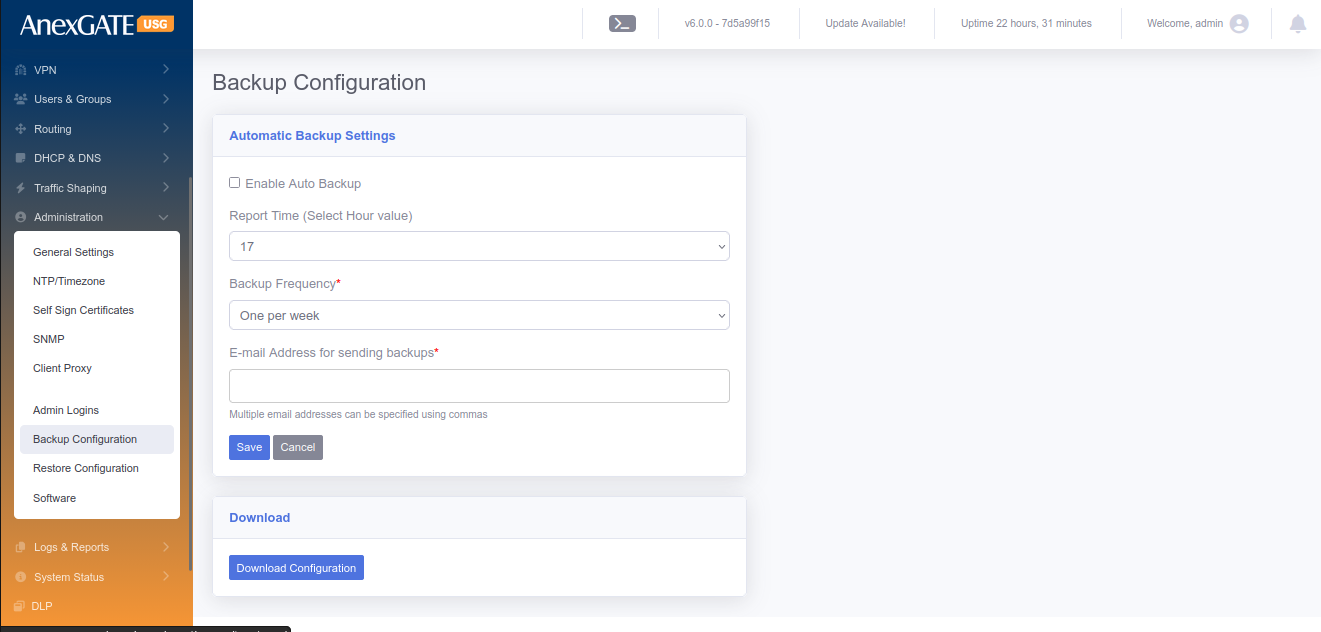
¶ 15.7 RESTORE CONFIGURATION
Configuration Backup file stored by downloading manually or setting up Automatic backup configuration can be used restore the configuration. Go to Admin > Restore configuration to restore the previously backed up Configuration file.
NOTE: The same backup configuration file can be used to restore configuration on mulitple AnexGATE Firewall USGs unless the build is same as the other devices.
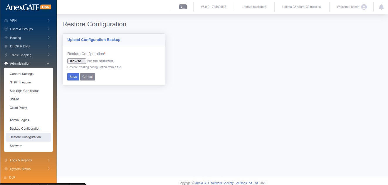
¶ 15.8 FIRMWARE UPDATE
AnexGATE USG Firewall firmware update can be done via ONLINE or OFFLINE using Firmware update .bin file provided by the AnexGATE personnel or available at the AnexGATE Partner Portal.
Go to Admin > Firmware Update to do offline update, download the respective Firmware update .bin file of the USG Firewall. Click on Choose file, select the bin file and Click Install. The update will take around 5-20 minutes depending on the update size.
NOTE: Every AnexGATE USG Firmware update .bin file is associated with its license key. So, firmware update must be downloaded accordingly with respect to the USG Firewall License. Basically, same Firmware Update .bin file cannot be used on other USG Firewall devices.
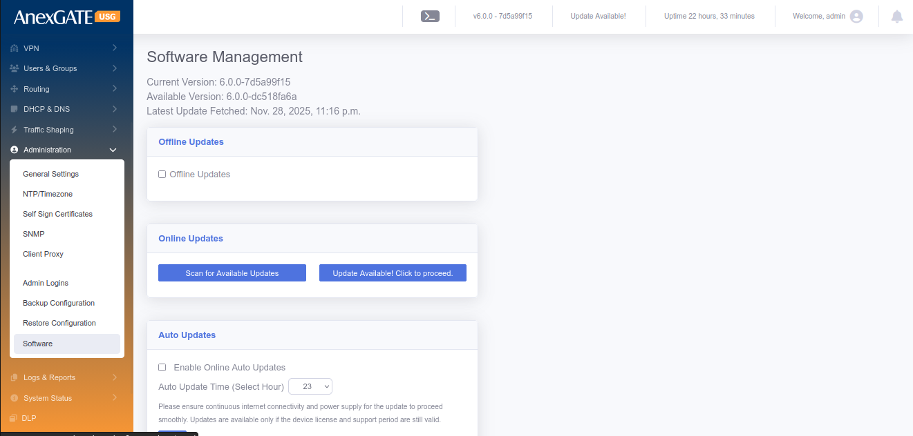
¶ 15.9 REBOOT
Go to Admin > Reboot. Click on Reboot, if the Firewall needs to be rebooted. This will take few minutes for the USG Firewall to stop all the services, reboot and run all the services again after reboot.
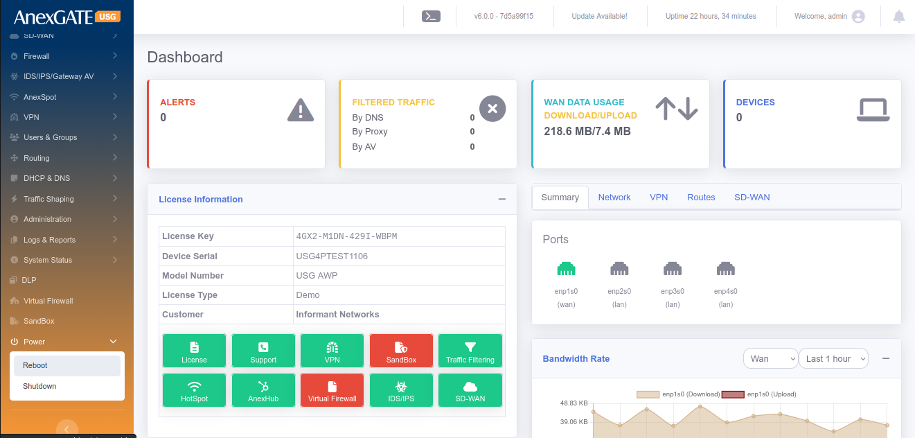
¶ 15.10 SHUTDOWN
Go to Admin > Shutdown. Click on Shutdown, if the Firewall needs to be shutdown. This will take few minutes for the USG Firewall to stop all the services and shutdown.
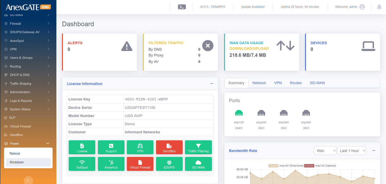
¶ 16. SUPPORT
¶ CONTACT
AnexGATE Technical Support
Email: support@anexgate.com
Mob: +91 87623 62577
Tel: +91 8042120774
Support for Customers without a AnexCARE Contract
Please contact or write an email to our AnexCARE team Email: sales@anexgate.com
Tel: +91 9066764493
Contact address:
AnexGATE Network Security Solution Pvt. Ltd. C/o Smile Security and Surveillance Pvt. Ltd.
#21/2, Bhattarahalli, Old Madras Road,
14 KM, K.R. Puram,
Bangalore-560 049. (INDIA)
© 2005-2021, Smile Security and Surveillance Pvt Ltd. All rights reserved. The SSSPL and AnexGATE logos are registered trademarks of Smile Security and Surveillance Pvt Ltd.
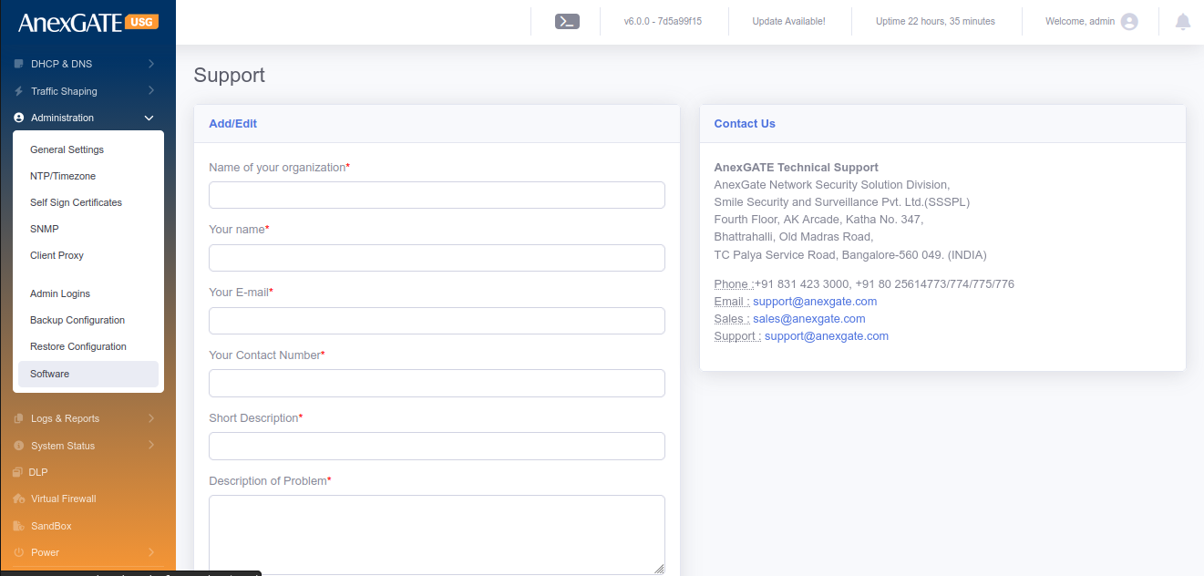
¶ 17. REPORTS
¶ 17.1 REPORT SETTINGS
¶ 17.1.1 CURRENT CONFIGURATION
PARAMETERS
| ELEMENTS | DESCRIPTION |
|---|---|
| Enable Link Alert | Enable this to send an alert if the link goes down to the mentioned email address. |
| Enable Reports | Enable this to receive reports to the mentioned email address. |
| Report Frequency | Select the frequency of receiving the reports in terms of a day, two per week, one per week, once every 2 weeks or one per month to your email address |
| E-mail Address for Report |
Add email address to receive the Link Alerts if enabled and reports. **Multiple email addresses can be specified using comma. |
| Options to be included in reports | Select the options from the list to be included in the report. For example: Top 25 Websites visited, Top 25 bandwidth consumers, Filtering voilations, user-wise/group-wise reports and so on. |
| SAVE | Save the Report Settings. |
¶ 17.1.2 GENERATE REPORT
PARAMETERS
| ELEMENTS | DESCRIPTION |
|---|---|
| Start Date/Time | Specify the start date and time for the report. |
| End Date/Time | Specify the end date and time for the report |
| Options to be included in reports | Select the options from the list to be included in the report. For example: Top 25 Websites visited, Top 25 bandwidth consumers, Filtering voilations, user-wise/group-wise reports and so on. |
| Specific Users | Select users if any, configured to receive user specific report. |
| Specific Groups | Select group if any, configured to receive group specific report. |
| Export |
Send via Email – Generate report and send directly to the email. Download PDF – Download the report in the PDF format. Show Report – Generate and show the report on the onsite webpage. |
| Generate | Click to generate the report. |
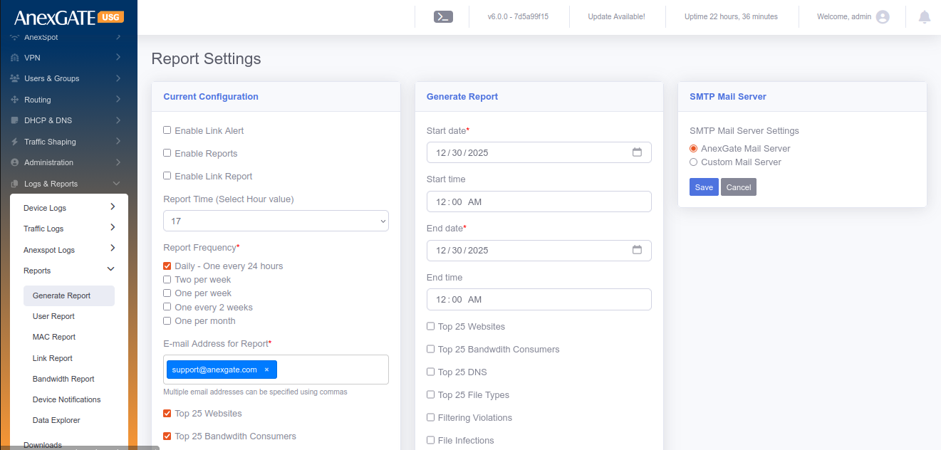
NOTE: If the user is lunable to generate report for larger duration, then adjust the timespan duration for short term to generate the file. This may also depend on how much data is accumulated in the mentioned period of time.
¶ 17.2 USER REPORT
User Report provides details of the traffic generated by the user’s IP address. At overview, it displays the IP address along with Upload/Download Statics. Clicking on the IP address highlighted in blue displays in-depth details such as HTTP/s sites visited, DNS Queries made, Connections established and so on.
User report can be viewed and downloaded in Excel or PDF format based on IPs by specifying Date/Time period.
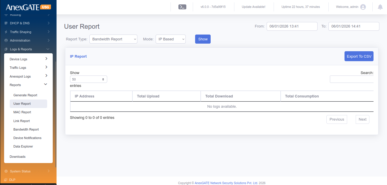
¶ 17.3 LINK REPORT
Link Report provides details of the link status of WAN links connected to the USG in terms of graphical representation. The report can be generated by specifing the WAN Interface (if multiple) and From/To Date & Time within a month.
Total LAN & WAN Statistics of upto 24hours will be displayed.
PARAMETERS
| ELEMENTS | DESCRIPTION |
|---|---|
| Interface Name | Displays the interface name of WAN link |
| Port Status | Displays the physical status of port being connected or disconnected. |
| Link Status | Displays the link status being ONLINE or OFFLINE wrt reachability. |
| Upload Rate | Displays upload rate |
| Download Rate | Displays download rate |
| Latency | Displays Latency |
|
D ate/Time |
Displays Date & Time |
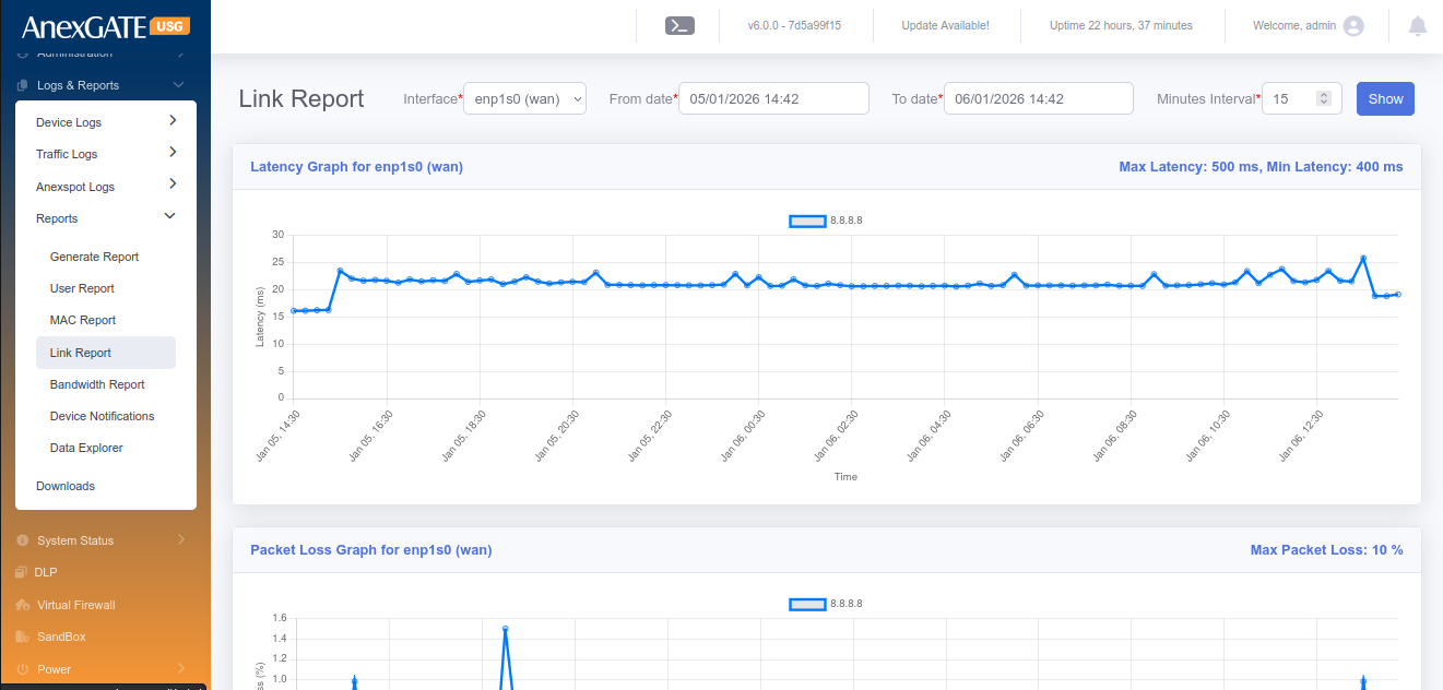
¶ 17.4 BANDWIDTH REPORT
Bandwidth Report provides details of the network usage rate. The Upload/Download bandwidth rate can be viewed in terms of graphical representation by selecting their respective interfaces (if multiple) and specifying From/To Date & Time.
Bandwidth Report can be viewed and downloaded in Excel and PDF Format.
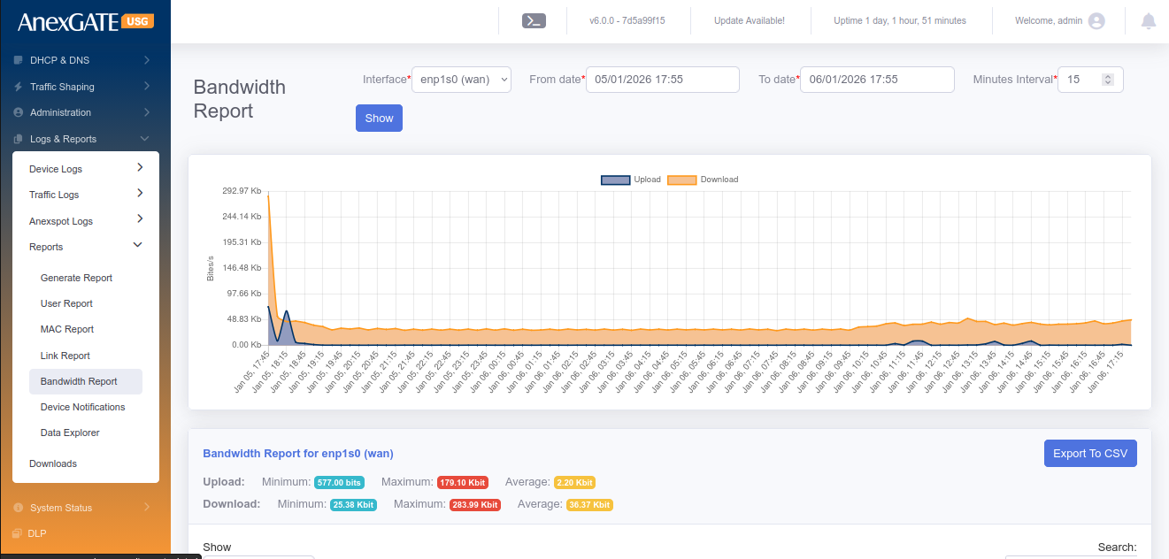
¶ 18. SETTINGS
¶ 18.1 LICENSE
To Configure/Update License, Go to Settings > License.
NOTE: License is required for the firewall to function as per requirement. Without License, the traffic will not be directed towards LAN. Keep a copy or save the license in a notepad before resetting the USG Firewall as you will need to re-enter the License Key and Device Serial Number under License tab.
PARAMETERS
| ELEMENTS | DESCRIPTION |
|---|---|
| License Key* | Enter License key provided by AnexGATE |
| MAC Address* | MAC Address of the appliance is displayed |
| Device Serial* | Enter Device Serial number written below at the bottom of the appliance |
| License Activation Mode | Choose Online or Offline Activation Mode. For Online mode Activation the internet is required for registration. |
| License Activation File (Offline Mode) | Choose Offline bin file provided by AnexGATE to activate the License in offline mode. |
| Check License | Click this to check the validity of the License |
| Re-Register License | Click this to re-register the License |
| SAVE | Save the License configuration Settings |
NOTE:
1. Check the License Information table after saving License settings to verify the License to be valid. The License Information displays all the information regarding the Firewall such as Device Info, License and support status, VPN limit, User limit of the firewall and so on.
2. Hotspot service corresponds to additional AnexSPOT service offered to the customer. If the Hotspot shows disabled in the License Information, then the AnexSPOT services is not available in the menu table. The service can be availed/enabled by contacting AnexGATE support.
3. Services or Status under License Information can only be changed by AnexGATE. If any services are to be acquired or discarded, send a mail to support@anexgate.com.
Unified Security Gateway Software License Agreement is mentioned below.

¶ 18.2 GENERAL
To configure General Settings in the Firewall, Go to Settings > General.
¶ 18.2.1 GENERIC SETTINGS
PARAMETERS
| ELEMENTS | DESCRIPTION |
|---|---|
| Device Hostname | Set a Device Hostname for the USG Firewall. |
| Enable Cloud Updates | Click this to enable cloud updates for USG Firewall. |
| Enable Anti-Virus Updates | Click this to enable Anti-Virus Updates. |
| Automatic Block Threats | Click this to enable block threats automatically |
| Allow Remote Troubleshooting | Click this to enable Remote Troubleshooting from AnexGATE Personnel. |
| DNS Filtering | Click this to enable DNS Filtering. |
| Torrent Filtering | Click this to filtering the Torrents. |
| Block High UDP Ports | Click this to Block high UDP ports. |
| WAN Ping | Click this to enable WAN Ping if static public IP is configured on USG. |
| Clamp MSS to Path MTU | Click this to automatically set the MSS to Path MTU in packets. |
| Multicast | Click this to enable Multicasting of traffic to parallel zones. Useful when configuring IPSec. |
| Accounting Update Internal (Mins)* | Enter a time in minutes on how frequently should the Traffic Accounting to be done. |
| Limit WAN Access to IPs | Provide Public IPs to limit WAN Access to the Firewall. Use comma to add Multiple IPs. |
| Allow Dashboard via WAN | Click this to Allow the Firewall Dashboard to be accessible via configured WAN IPs. |
| Dashboard Port |
Specify port to access Firewall. Default Port = 4443 To access the firewall, type URL : https://192.168.100.1:4443 |
| Management Port* | Specify port to access Firewall Backend via SSH. Default Port = 2299 |
| Maximum Login Attempts* | Assign Number of attempts allowed to login incase of invalid username or password. |
| Lockout Time Period in Seconds* | Assign Lockout Time incase invalid credentials are provided more than the times mentoned in Maximum Login Attempts |
| Logging Level* | Choose the Logging mode for Firewall |
| SAVE | Save the Generic Firewall configuration settings |
¶ 18.2.2 SNMP SETTINGS
Snmp can be configured under Settings > General. Basic SNMP protocols such as v2 & v3 are supported.
PARAMETERS
| ELEMENTS | DESCRIPTION |
|---|---|
| Name* | Specify a name to identify the agent. |
| Description* | Add an agent Description. |
| Port* | Specify the port which the USG should use to send traps. Default = 161 |
| Authentication Protocol* | Choose MD5 or SHA as authentication protocol. |
| Authentication Password* | Assign Authentication Password. |
| Privacy Protocol* | Choose AES or DES as privacy protocol. |
| Privacy Password* | Provide Privacy Password. |
| SAVE | Save the SNMP configuration settings. |
¶ 18.2.3 SYSLOG EXPORT
Syslog export can be configured under Settings > General.
PARAMETERS
| ELEMENTS | DESCRIPTION |
|---|---|
| Status | Enable or Disable the Syslog Export to the server |
| Server IP Address* | Provide IP Address of the syslog server |
| Server Port* | Provide the syslog server listening port |
| Protocol* | Select TCP or UDP Protocol |
| Severity Levels | Select the Severity level to be exported to syslog server |
| Logs | Select the logs to be exported to syslog server |
| SAVE | Save the Syslog Export configuration settings. |
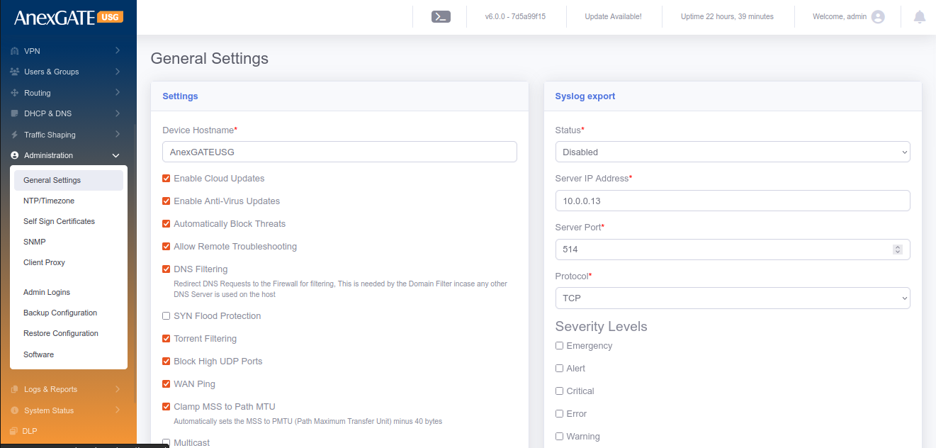
¶ 18.3 NTP / TIMEZONE
To configure USG Firewall current date and time synchronised with an NTP Server, Go to Settings > General > NTP/Timezone.
PARAMETERS
| ELEMENTS | DESCRIPTION |
|---|---|
| Current Time | Displays the current system time of USG Firewall. |
| TimeZone* | Select the timezone according to the geographical region in which the USG Firewall is deployed. |
| First Server | Specify the first NTP Server IP Address or domain name to sync time. Default – time.nist.gov |
| Second Server | Specify the second NTP Server IP Address or domain name to sync time. Default – 0.in.pool.ntp.org |
| Third Server | Specify the third NTP Server IP Address or domain name to sync time. Default – time.google.com |
| SAVE | Save the NTP/Timezone configuration settings. |
19. SYSTEM INFORMATION
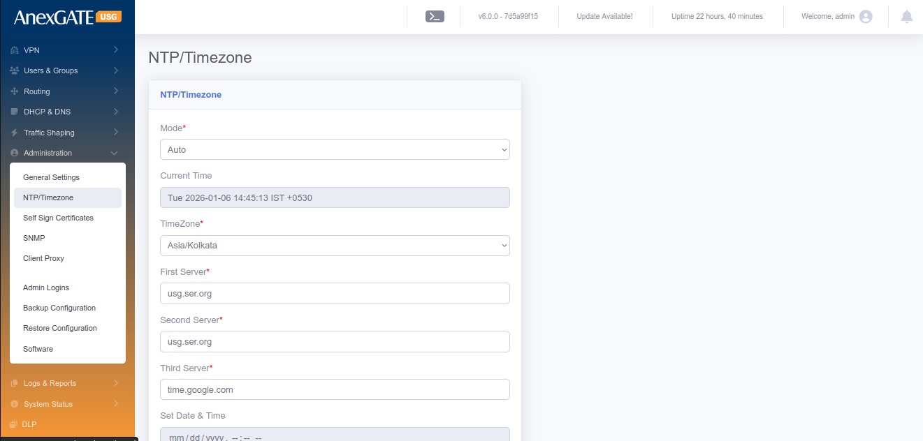
¶ 19.1 SYSTEM STATUS
System status displays the current status of the services running inside the USG Firewall. To restart specific individual services which are being used by the firewall. Go to System Information > System Status.
The Current Status tab shows if the respective service is in ONLINE or OFFLINE status.
The Action tab provides ability to restart the particular services mentioned in the Service column.
PARAMETERS
| SERVICES | DESCRIPTION |
|---|---|
| Dashboard | Restart the UI Dashboard service. |
| Middleware | Restart the middleware service which is intermediatary to UI and Database. |
| IPS Controller | Restart Alert Dynamic IP show service. |
| HTTP/HTTPS Proxy | Restart Proxy Service if running. |
| Logging Agent | Restart Logging Agent service. |
| IDS/IPS Engine | Restart the IDS/IPS Engine. |
| SSL VPN Server | Restart the SSL VPN Server. |
| IPSec | Restart the IPSec Service. |
| Database | Restart the DATABASE service of the USG. |
| Firewall Engine | Restart the Firewall rules & policy service of the USG |
| DHCP Server | Restart the DHCP Server. |
| DNS Server | Restart the DNS Server. |
| AnexSPOT | Restart the AnexSPOT service if supported by the USG. |
| Filtering Engine | Restart the Web Filtering service. |
PHYSICAL PORT STATUS
Physical Port Status displays the overview of the LAN/WAN link in terms of Connected or Disconnected status with respect to the Bandwidth speed that the link is supported.
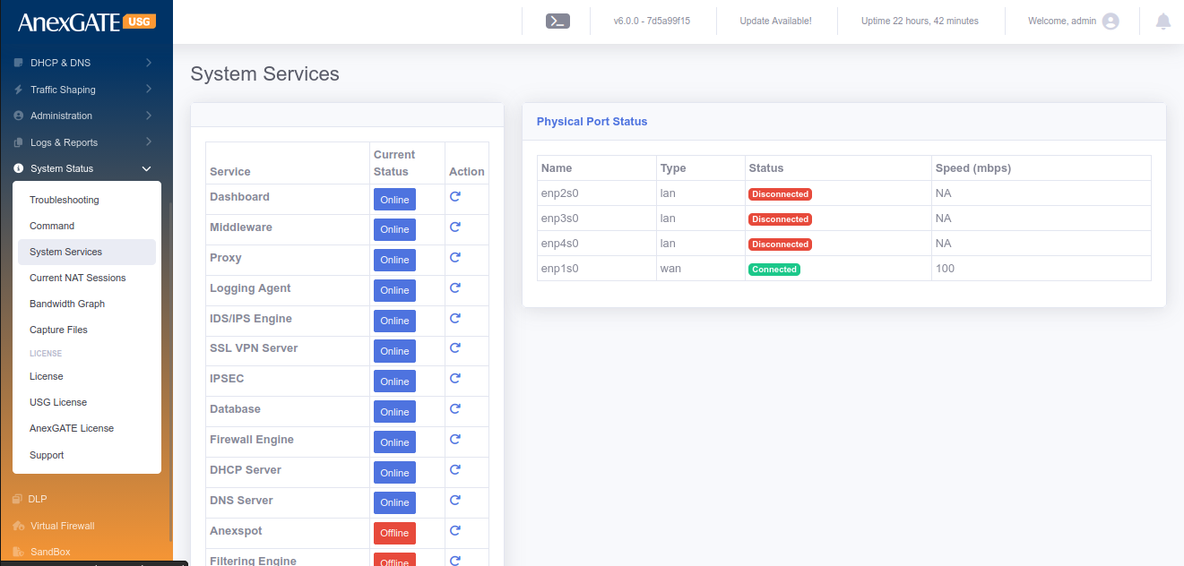
¶ 19.2 USG LICENSE
Overview of End User License Agreement and AnexGATE Usage License.
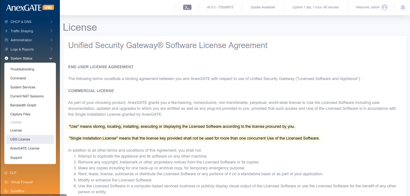
¶ 19.3 ANEXGATE LICENSE
As part of your choosing product, AnexGATE grants you a fee-bearing, nonexclusive, non-transferable, perpetual, world-wide license to Use the Licensed Software including user documentation, updates and upgrades to which you are entitled as well as any plug-ins provided to you, provided that such access and Use of the Licensed Software is in accordance with the Single Installation License granted by AnexGATE.
"Use" means storing, locating, installing, executing or displaying the Licensed Software according to the license procured by you.
"Single Installation License" means that the license key provided shall not be used for more than one concurrent Use of the Licensed Software.
In addition to all other terms and conditions of this Agreement, you shall not:
1. Attempt to duplicate the appliance and its software on any other machine;
2. Remove any copyright, trademark or other proprietary notices from the Licensed Software or its copies;
3. Make any copies including for one back-up or archival copy, for temporary emergency purpose;
4. Rent, lease, license, sublicense or distribute the Licensed Software or any portions of it on a standalone basis or as part of your application;
5. Modify or enhance the Licensed Software;
6. Use the Licensed Software in a computer-based services business or publicly display visual output of the Licensed Software or use the Licensed Software for the benefit of any other person or entity;
7. Reverse engineer, decompile or disassemble the Licensed Software; or
8. Allow any third parties to access, use or support the Licensed Software.
As part of subscription license, AnexGATE provides support that includes email support for problem reporting and online access to product documentation at no additional cost for the period of subscription. Technical Support is not included as part of license. You may purchase technical support services for perpetual license by paying the then current maintenance and support fee which would include product updates, upgrades and other improvements.